Toyota Venza: Removal
REMOVAL
PROCEDURE
1. REMOVE REAR DOOR SCUFF PLATE RH
HINT:
Use the same procedure for the RH side and the LH side (See page
.gif) ).
).
2. REMOVE REAR DOOR OPENING TRIM WEATHERSTRIP RH
HINT:
Use the same procedure for the RH side and the LH side (See page
).
3. REMOVE TONNEAU COVER ASSEMBLY (w/ Tonneau Cover)
4. REMOVE DECK BOARD ASSEMBLY
5. REMOVE NO. 3 DECK BOARD SUB-ASSEMBLY
6. REMOVE DECK SIDE TRIM BOX LH
7. REMOVE NO. 2 DECK BOARD SUB-ASSEMBLY
8. REMOVE DECK SIDE TRIM BOX RH
9. REMOVE NO. 1 DECK BOARD
10. REMOVE REAR SEAT SUB FLOOR PANEL ASSEMBLY
11. REMOVE REAR FLOOR FINISH PLATE
12. REMOVE REAR SEAT HEADREST ASSEMBLY
13. REMOVE REAR SEAT CENTER HEADREST ASSEMBLY
14. REMOVE REAR SEAT INNER TRACK BRACKET COVER
15. REMOVE REAR SEAT OUTER TRACK BRACKET COVER
16. DISCONNECT REAR SEAT RECLINING CONTROL CABLE
17. REMOVE REAR SEAT ASSEMBLY RH
18. REMOVE RECLINING REMOTE CONTROL BEZEL RH
HINT:
Use the same procedure for the RH side and the LH side (See page
).
19. REMOVE LUGGAGE HOLD BELT STRIKER ASSEMBLY
HINT:
Use the same procedure for the RH side and the LH side (See page
).
20. DISCONNECT REAR SEAT OUTER BELT ASSEMBLY RH
HINT:
Use the same procedure for the RH side and the LH side (See page
).
21. REMOVE DECK TRIM SIDE PANEL ASSEMBLY RH
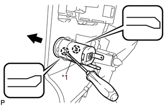
22. REMOVE REAR POWER POINT SOCKET ASSEMBLY
|
(a) Using a screwdriver, disengage the 2 claws and remove the rear power point socket assembly as shown in the illustration. Text in Illustration
HINT: Tape the screwdriver tip before use. |
|
23. REMOVE REAR POWER POINT SOCKET COVER
|
(a) Disengage the 2 claws and remove the rear power point socket cover. |
|
.png)
 Installation
INSTALLATION
PROCEDURE
1. INSTALL REAR POWER POINT SOCKET COVER
(a) Engage the 2 claws to install the rear power point socket cover.
2. IN ...
 Seat
Seat
...
Other materials about Toyota Venza:
Diagnosis System
DIAGNOSIS SYSTEM
1. DESCRIPTION
(a) Lighting system data can be read from the Data Link Connector 3 (DLC3) of
the vehicle. When the system seems to be malfunctioning, use the Techstream to check
for malfunctions and perform repairs.
2. CHECK DLC3
(a) C ...
Display does not Dim when Light Control Switch is Turned ON
PROCEDURE
1.
CHECK IMAGE QUALITY SETTING
(a) Turn the light control switch to the tail or head position.
(b) Check that the daytime screen setting on the display adjustment screen is
set to on.
Result
...
Accelerator Pedal
Components
COMPONENTS
ILLUSTRATION
On-vehicle Inspection
ON-VEHICLE INSPECTION
PROCEDURE
1. INSPECT ACCELERATOR PEDAL SENSOR ASSEMBLY
(a) Connect the Techstream to the DLC3.
(b) Turn the ignition switch to ON.
(c) Turn the Techstream on.
(d) En ...

0.1488