Toyota Venza: Reassembly
REASSEMBLY
PROCEDURE
1. INSTALL FRONT DIFFERENTIAL CASE REAR TAPERED ROLLER BEARING
|
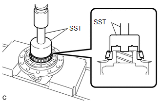
(a) Using SST and a press, install a new front differential case rear tapered roller bearing (inner race) to the front differential case. SST: 09726-36010 SST: 09950-70010 09951-07100 NOTICE:
|
|
|
(b) Using SST and a hammer, install a new front differential case rear tapered roller bearing (outer race) to the transaxle case sub-assembly. SST: 09950-60020 09951-00890 SST: 09950-70010 09951-07150 NOTICE: Ensure that there is no clearance between the front differential case rear tapered roller bearing (outer race) and transaxle case sub-assembly. |
|
2. INSTALL FRONT DIFFERENTIAL CASE FRONT TAPERED ROLLER BEARING
|
(a) Using SST and a press, install a new front differential case front tapered roller bearing (inner race) to the front differential case. SST: 09710-30012 09710-04081 SST: 09950-60010 09951-00480 SST: 09950-70010 09951-07100 NOTICE:
|
|

(b) Install the shim to the transaxle housing.
|
(c) Using SST and a hammer, install a new front differential case front tapered roller bearing (outer race) to the transaxle housing. SST: 09950-60020 09951-00890 SST: 09950-70010 09951-07150 NOTICE: Ensure that there is no clearance between the front differential case front tapered roller bearing (outer race), shim and transaxle housing. |
|
3. INSTALL FRONT DIFFERENTIAL SIDE GEAR
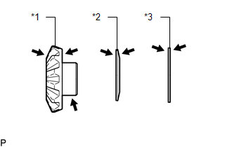
(a) Coat the front differential side gear, front No. 1 differential side gear thrust washer and conical spring with ATF.
 Text in Illustration
|
*1 |
Front Differential Side Gear |
|
*2 |
Conical Spring |
|
*3 |
Front No. 1 Differential Side Gear Thrust Washer |
.png) |
ATF |
|
(b) Install the 2 front differential side gears, 2 front No. 1 differential side gear thrust washers and 2 conical springs to the front differential case. Text in Illustration
NOTICE:
|
|
.png)
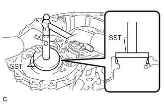
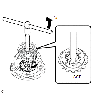
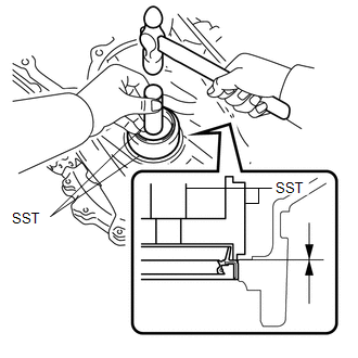
(c) Install SST as shown in the illustration and tighten it.
.png) Text in Illustration
Text in Illustration
|
*a |
Turn |
*b |
Hold |
SST: 09528-52010
09528-05010
09953-05010
NOTICE:
Do not overtighten SST as doing so will damage the front differential side gears, conical springs, front No. 1 differential side gear thrust washers and front differential case.
HINT:
- Tighten SST to create the necessary clearance to install the front differential pinions.
- When installing the front differential pinions, do not overtighten SST, as it is necessary to rotate the front differential side gears.
(d) Coat the front differential pinion and front differential pinion thrust washer with ATF.
 Text in Illustration
|
|
ATF |
|
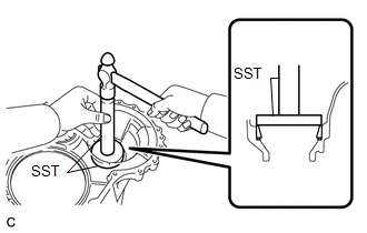
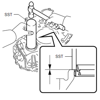
(e) Using SST as shown in the illustration, rotate the front differential side gear to install the 2 front differential pinions and 2 front differential pinion thrust washers. Text in Illustration
SST: 09528-52010 09528-05030 CAUTION: Be careful not to catch your fingers between the front differential pinion and front differential case. NOTICE: Do not drop the front differential pinion or front differential pinion thrust washer. |
|
4. INSPECT FRONT DIFFERENTIAL PINION BACKLASH
.gif)
5. INSTALL FRONT NO. 1 DIFFERENTIAL PINION SHAFT
(a) Coat the front No. 1 differential pinion shaft with ATF.
 Text in Illustration
|
|
ATF |
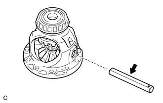
(b) Install the front No. 1 differential pinion shaft to the front differential case so that the hole for the front differential pinion shaft straight pin is aligned with the hole in the front differential case.
6. INSPECT FRONT DIFFERENTIAL CASE
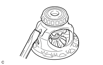
7. INSTALL FRONT DIFFERENTIAL PINION SHAFT STRAIGHT PIN
|
(a) Using a 5 mm pin punch and a hammer, install the front differential pinion shaft straight pin to the front differential case. |
|
|
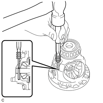
(b) Using a chisel and hammer, stake the front differential case. |
|
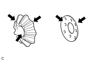
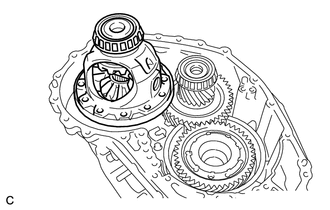
8. ADJUST DIFFERENTIAL SIDE BEARING PRELOAD
(a) Remove any remaining seal packing from the contact surfaces of the transaxle housing and transaxle case sub-assembly.
|
(b) Install the front differential case to the transaxle case sub-assembly. |
|
|
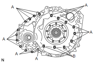
(c) Install the transaxle housing to the transaxle case sub-assembly with the 20 bolts. Torque: Bolt (A) : 31 N·m {312 kgf·cm, 23 ft·lbf} Bolt (B) : 23 N·m {231 kgf·cm, 17 ft·lbf} |
|
|
(d) Using SST, turn the front differential case right and left 2 or 3 times to settle the bearings. SST: 09564-33010 |
|
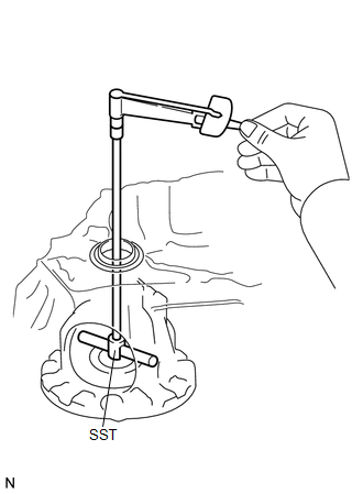
(e) Using SST and a torque wrench, measure the turning torque of the differential side bearing while rotating SST at 10 rpm.
SST: 09564-33010
Turning Torque:
0.8 to 1.4 N*m (8 to 14 kgf*cm, 7 to 12 in.*lbf)
If the turning torque is not within the specified range, refer to the table below to select a shim so that the turning torque is within the specified range.
Shim Thickness|
Part No. |
Thickness (mm (in.)) |
|---|---|
|
90564-A0106 |
2.000 (0.0787) |
|
90564-A0107 |
2.025 (0.0797) |
|
90564-A0108 |
2.050 (0.0807) |
|
90564-A0109 |
2.075 (0.0817) |
|
90564-A0110 |
2.100 (0.0827) |
|
90564-A0111 |
2.125 (0.0837) |
|
90564-A0112 |
2.150 (0.0846) |
|
90564-A0113 |
2.175 (0.0856) |
|
90564-A0114 |
2.200 (0.0866) |
|
90564-A0115 |
2.225 (0.0876) |
|
90564-A0116 |
2.250 (0.0886) |
|
90564-A0117 |
2.275 (0.0896) |
|
90564-A0118 |
2.300 (0.0906) |
|
90564-A0119 |
2.325 (0.0915) |
|
90564-A0120 |
2.350 (0.0925) |
|
90564-A0121 |
2.375 (0.0935) |
|
90564-A0122 |
2.400 (0.0945) |
|
90564-A0123 |
2.425 (0.0955) |
|
90564-A0124 |
2.450 (0.0965) |
|
90564-A0125 |
2.475 (0.0974) |
|
90564-A0126 |
2.500 (0.0984) |
|
90564-A0127 |
2.525 (0.0994) |
|
90564-A0128 |
2.550 (0.100) |
|
90564-A0129 |
2.575 (0.101) |
|
90564-A0130 |
2.600 (0.102) |
|
90564-A0131 |
2.625 (0.103) |
|
90564-A0132 |
2.650 (0.104) |
|
90564-A0133 |
2.675 (0.105) |
|
90564-A0134 |
2.700 (0.106) |
|
90564-A0135 |
2.725 (0.107) |
|
90564-A0136 |
2.750 (0.108) |
|
90564-A0137 |
2.775 (0.109) |
|
90564-A0138 |
2.800 (0.110) |
|
90564-A0139 |
2.825 (0.111) |
|
90564-A0140 |
2.850 (0.112) |
|
90564-A0141 |
2.875 (0.113) |
|
(f) Remove the 20 bolts and transaxle housing from the transaxle case sub-assembly. |
|
.png)
|
(g) Remove the front differential case from the transaxle case sub-assembly. |
|
9. INSTALL FRONT DIFFERENTIAL RING GEAR
|
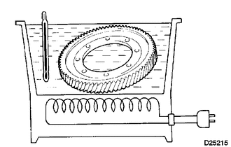
(a) Using ATF and a heater, heat the front differential ring gear to 90 to 110°C (194 to 230°F). NOTICE: Do not heat the front differential ring gear to more than 110°C (230°F). |
|
|
(b) Clean the contact surface of the front differential case. Text in Illustration
|
|
.png)
(c) Align the matchmarks, and install the front differential ring gear to the front differential case quickly.
|
(d) Install the 12 bolts. Torque: 120 N·m {1224 kgf·cm, 89 ft·lbf} NOTICE:
|
|
.png)
10. INSTALL TRANSAXLE CASE OIL SEAL
(a) Coat the lip of a new transaxle case oil seal with MP grease.
|
(b) Using SST and a hammer, install the transaxle case oil seal to the transaxle case sub-assembly. SST: 09316-10010 SST: 09950-70010 09951-07100 Standard Depth: -0.5 to 0.5 mm (-0.0197 to 0.0197 in.) NOTICE:
|
|
11. INSTALL FRONT TRANSAXLE CASE OIL SEAL
|
(a) Coat the lip of a new front transaxle case oil seal with MP grease. |
|
(b) Using SST and a hammer, install the front transaxle case oil seal to the transaxle housing.
SST: 09308-14010
Standard Depth:
-0.5 to 0.5 mm (-0.0197 to 0.0197 in.)
NOTICE:
- Make sure that the front transaxle case oil seal is installed in the correct direction.
- Do not damage the lip of the front transaxle case oil seal.
 Inspection
INSPECTION
PROCEDURE
1. INSPECT FRONT DIFFERENTIAL CASE
(a) Using SST, rotate the front differential side gear as shown in the
illustration.
SST: 09528-52010
09528-05030
Sta ...
 Differential Oil Seal
Components
COMPONENTS
ILLUSTRATION
Replacement
REPLACEMENT
PROCEDURE
1. DRAIN AUTOMATIC TRANSAXLE FLUID
(a) Remove the No. 2 engine under cover and front fender apron LH.
(b) ...
Other materials about Toyota Venza:
Headlight Solenoid Circuit
DESCRIPTION
for HID Headlight:
When the main body ECU receives a high beam turn on signal, the main
body ECU activates the bi-function by controlling the BI-XENON relay. The
bi-function increases the upper illumination area of the discharge ...
Terminals Of Ecu
TERMINALS OF ECU
1. STEERING LOCK ECU (STEERING LOCK ACTUATOR ASSEMBLY)
Terminal No. (Symbol)
Wiring Color
Terminal Description
Condition
Specified Condition
D17-1 (GND) - Body ground
...
System Description
SYSTEM DESCRIPTION
1. LIN COMMUNICATION SYSTEM DESCRIPTION
The LIN communication system is used for communication between the components
in the table below. If communication cannot be performed through LIN communication
because of an open in the communic ...

0.14