Toyota Venza: Short in Passenger Side Airbag Variable Vent Hole Squib Circuit (B181A/7A-B181D/7A)
DESCRIPTION
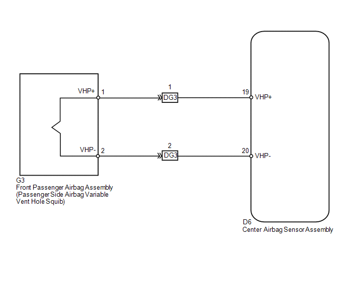
The passenger side airbag variable vent hole squib circuit consists of the center airbag sensor assembly and front passenger airbag assembly.
The center airbag sensor assembly uses this circuit to deploy the airbag when deployment conditions are met.
These DTCs are stored when a malfunction is detected in the passenger side airbag variable vent hole squib circuit.
|
DTC No. |
DTC Detection Condition |
Trouble Area |
|---|---|---|
|
B181A/7A |
|
|
|
B181B/7A |
|
|
|
B181C/7A |
|
|
|
B181D/7A |
|
|
WIRING DIAGRAM
CAUTION / NOTICE / HINT
HINT:
- Perform the simulation method by selecting check mode (Signal Check)
using the Techstream (See page
.gif) ).
).
- After selecting check mode (Signal Check), perform the simulation method
by wiggling each connector of the airbag system or driving the vehicle on
a city road or rough road (See page
).
PROCEDURE
|
1. |
CHECK CONNECTORS |
|
(a) Turn the ignition switch off. |
|
.png)
(b) Disconnect the cable from the negative (-) battery terminal, and wait for at least 90 seconds.
(c) Check that the connectors are properly connected to the front passenger airbag assembly and center airbag sensor assembly. Also check that the connectors that link the instrument panel wire and instrument panel wire assembly are properly connected.
OK:
The connectors are properly connected.
HINT:
If the connectors are not connected securely, reconnect the connectors and proceed to the next inspection.
(d) Disconnect the connectors from the front passenger airbag assembly and center airbag sensor assembly. Also disconnect the instrument panel wire from the instrument panel wire assembly.
(e) Check that the terminals of the connectors are not damaged.
OK:
The terminals are not deformed or damaged.
(f) Check that the instrument panel wire assembly connector (on the front passenger airbag assembly side) is not damaged.
OK:
The lock button is not disengaged, and the claw of the lock is not deformed or damaged.
(g) Check that the short springs for the instrument panel wire and instrument panel wire assembly with the activation prevention mechanism are not deformed or damaged.
OK:
The short springs are not deformed or damaged.
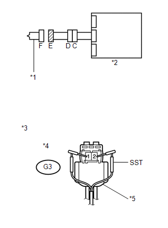
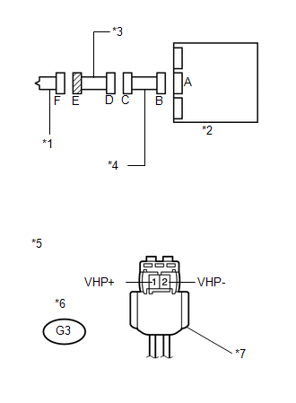
Text in Illustration|
*1 |
Passenger Side Airbag Variable Vent Hole Squib |
|
*2 |
Center Airbag Sensor Assembly |
|
*3 |
Instrument Panel Wire Assembly |
|
*4 |
Instrument Panel Wire |
| NG | .gif) |
REPLACE WIRE HARNESS |
|
.gif)
|
2. |
CHECK FRONT PASSENGER AIRBAG ASSEMBLY (PASSENGER SIDE AIRBAG VARIABLE VENT HOLE SQUIB) |
|
(a) Connect the instrument panel wire to the instrument panel wire assembly and center airbag sensor assembly. |
|
(b) Connect SST (resistance 2.1 Ω) to connector E (green connector).
CAUTION:
Never connect the tester to the front passenger airbag assembly (passenger side airbag variable vent hole squib) for measurement, as this may lead to a serious injury due to airbag deployment.
NOTICE:
- Do not forcibly insert SST into the terminals of the connector when connecting.
- Insert SST straight into the terminals of the connector.
SST: 09843-18061
(c) Connect the cable to the negative (-) battery terminal.
(d) Clear the DTCs stored in memory (See page
).
(e) Turn the ignition switch off.
(f) Turn the ignition switch to ON, and wait for at least 60 seconds.
(g) Check for DTCs (See page ).
OK:
DTC B181A, B181B, B181C, B181D or 7A is not output.
HINT:
Codes other than DTCs B181A, B181B, B181C, B181D and 7A may be output at this time, but they are not related to this check.
(h) Turn the ignition switch off.
(i) Disconnect the cable from the negative (-) battery terminal, and wait for at least 90 seconds.
(j) Disconnect SST from connector E.
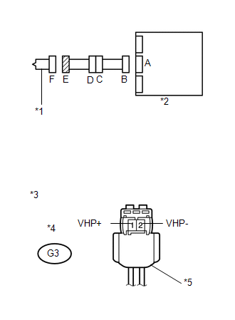
Text in Illustration|
*1 |
Passenger Side Airbag Variable Vent Hole Squib |
|
*2 |
Center Airbag Sensor Assembly |
|
*3 |
Front view of wire harness connector (to Passenger Side Airbag Variable Vent Hole Squib) |
|
*4 |
Connector E |
|
*5 |
Color: Green |
| OK | |
REPLACE FRONT PASSENGER AIRBAG ASSEMBLY |
|
|
3. |
CHECK PASSENGER SIDE AIRBAG VARIABLE VENT HOLE SQUIB CIRCUIT |
|
(a) Disconnect the instrument panel wire from the center airbag sensor assembly. |
|
(b) Check for a short to B+ in the circuit.
(1) Connect the cable to the negative (-) battery terminal.
(2) Turn the ignition switch to ON.
(3) Measure the voltage according to the value(s) in the table below.
Standard Voltage:
|
Tester Connection |
Switch Condition |
Specified Condition |
|---|---|---|
|
G3-1 (VHP+) - Body ground |
Ignition switch ON |
Below 1 V |
|
G3-2 (VHP-) - Body ground |
Ignition switch ON |
Below 1 V |
(c) Check for an open in the circuit.
(1) Turn the ignition switch off.
(2) Disconnect the cable from the negative (-) battery terminal, and wait for at least 90 seconds.
(3) Measure the resistance according to the value(s) in the table below.
Standard Resistance:
|
Tester Connection |
Condition |
Specified Condition |
|---|---|---|
|
G3-1 (VHP+) - G3-2 (VHP-) |
Always |
Below 1 Ω |
(d) Check for a short to ground in the circuit.
(1) Measure the resistance according to the value(s) in the table below.
Standard Resistance:
|
Tester Connection |
Condition |
Specified Condition |
|---|---|---|
|
G3-1 (VHP+) - Body ground |
Always |
1 MΩ or higher |
|
G3-2 (VHP-) - Body ground |
Always |
1 MΩ or higher |
(e) Check for a short in the circuit.
(1) Release the activation prevention mechanism built into connector B (See page
).
(2) Measure the resistance according to the value(s) in the table below.
Standard Resistance:
|
Tester Connection |
Condition |
Specified Condition |
|---|---|---|
|
G3-1 (VHP+) - G3-2 (VHP-) |
Always |
1 MΩ or higher |
(f) Restore the released activation prevention mechanism of connector B to the original condition.
Text in Illustration|
*1 |
Passenger Side Airbag Variable Vent Hole Squib |
|
*2 |
Center Airbag Sensor Assembly |
|
*3 |
Front view of wire harness connector (to Passenger Side Airbag Variable Vent Hole Squib) |
|
*4 |
Connector E |
|
*5 |
Color: Green |
| NG | |
GO TO STEP 5 |
|
|
4. |
CHECK CENTER AIRBAG SENSOR ASSEMBLY |
|
(a) Connect the connectors to the front passenger airbag assembly and center airbag sensor assembly. |
|
.png)
(b) Connect the cable to the negative (-) battery terminal.
(c) Clear the DTCs stored in memory (See page
).
(d) Turn the ignition switch off.
(e) Turn the ignition switch to ON, and wait for at least 60 seconds.
(f) Check for DTCs (See page ).
OK:
DTC B181A, B181B, B181C, B181D or 7A is not output.
HINT:
Codes other than DTCs B181A, B181B, B181C, B181D and 7A may be output at this time, but they are not related to this check.
Text in Illustration|
*1 |
Passenger Side Airbag Variable Vent Hole Squib |
|
*2 |
Center Airbag Sensor Assembly |
| OK | |
USE SIMULATION METHOD TO CHECK |
| NG | |
REPLACE CENTER AIRBAG SENSOR ASSEMBLY |
|
5. |
CHECK INSTRUMENT PANEL WIRE |
|
(a) Disconnect the instrument panel wire assembly from the instrument panel wire. |
|
(b) Check for a short to B+ in the circuit.
(1) Connect the cable to the negative (-) battery terminal.
(2) Turn the ignition switch to ON.
(3) Measure the voltage according to the value(s) in the table below.
Standard Voltage:
|
Tester Connection |
Switch Condition |
Specified Condition |
|---|---|---|
|
DG3-1 (VHP+) - Body ground |
Ignition switch ON |
Below 1 V |
|
DG3-2 (VHP-) - Body ground |
Ignition switch ON |
Below 1 V |
(c) Check for an open in the circuit.
(1) Turn the ignition switch off.
(2) Disconnect the cable from the negative (-) battery terminal, and wait for at least 90 seconds.
(3) Measure the resistance according to the value(s) in the table below.
Standard Resistance:
|
Tester Connection |
Condition |
Specified Condition |
|---|---|---|
|
DG3-1 (VHP+) - DG3-2 (VHP-) |
Always |
Below 1 Ω |
(d) Check for a short to ground in the circuit.
(1) Measure the resistance according to the value(s) in the table below.
Standard Resistance:
|
Tester Connection |
Condition |
Specified Condition |
|---|---|---|
|
DG3-1 (VHP+) - Body ground |
Always |
1 MΩ or higher |
|
DG3-2 (VHP-) - Body ground |
Always |
1 MΩ or higher |
(e) Check for a short in the circuit.
(1) Release the activation prevention mechanism built into connector B (See page
).
(2) Measure the resistance according to the value(s) in the table below.
Standard Resistance:
|
Tester Connection |
Condition |
Specified Condition |
|---|---|---|
|
DG3-1 (VHP+) - DG3-2 (VHP-) |
Always |
1 MΩ or higher |
(3) Restore the released activation prevention mechanism of connector B to the original condition.
Text in Illustration|
*1 |
Passenger Side Airbag Variable Vent Hole Squib |
|
*2 |
Center Airbag Sensor Assembly |
|
*3 |
Instrument Panel Wire Assembly |
|
*4 |
Instrument Panel Wire |
|
*5 |
Front view of wire harness connector (to Instrument Panel Wire Assembly) |
|
*6 |
Connector C |
| NG | |
REPLACE INSTRUMENT PANEL WIRE |
|
|
6. |
CHECK INSTRUMENT PANEL WIRE ASSEMBLY |
|
(a) Check for a short to B+ in the circuit. (1) Connect the cable to the negative (-) battery terminal. (2) Turn the ignition switch to ON. (3) Measure the voltage according to the value(s) in the table below. Standard Voltage:
|
|
(b) Check for an open in the circuit.
(1) Turn the ignition switch off.
(2) Disconnect the cable from the negative (-) battery terminal, and wait for at least 90 seconds.
(3) Measure the resistance according to the value(s) in the table below.
Standard Resistance:
|
Tester Connection |
Condition |
Specified Condition |
|---|---|---|
|
G3-1 (VHP+) - G3-2 (VHP-) |
Always |
Below 1 Ω |
(c) Check for a short to ground in the circuit.
(1) Measure the resistance according to the value(s) in the table below.
Standard Resistance:
|
Tester Connection |
Condition |
Specified Condition |
|---|---|---|
|
G3-1 (VHP+) - Body ground |
Always |
1 MΩ or higher |
|
G3-2 (VHP-) - Body ground |
Always |
1 MΩ or higher |
(d) Check for a short in the circuit.
(1) Release the activation prevention mechanism built into connector D (See page
).
(2) Measure the resistance according to the value(s) in the table below.
Standard Resistance:
|
Tester Connection |
Condition |
Specified Condition |
|---|---|---|
|
G3-1 (VHP+) - G3-2 (VHP-) |
Always |
1 MΩ or higher |
(3) Restore the released activation prevention mechanism of connector D to the original condition.
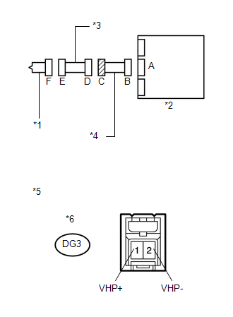
Text in Illustration|
*1 |
Passenger Side Airbag Variable Vent Hole Squib |
|
*2 |
Center Airbag Sensor Assembly |
|
*3 |
Instrument Panel Wire Assembly |
|
*4 |
Instrument Panel Wire |
|
*5 |
Front view of wire harness connector (to Passenger Side Airbag Variable Vent Hole Squib) |
|
*6 |
Connector E |
|
*7 |
Color: Green |
| OK | |
USE SIMULATION METHOD TO CHECK |
| NG | |
REPLACE INSTRUMENT PANEL WIRE ASSEMBLY |
 Short in Front Passenger Side Squib 2nd Step Circuit (B1815/54-B1818/54)
DESCRIPTION
The front passenger side squib 2nd step circuit consists of the center airbag
sensor assembly and front passenger airbag assembly.
The center airbag sensor assembly uses this circuit t ...
 Short in Side Squib RH Circuit (B1820/55-B1823/55)
DESCRIPTION
The side squib RH circuit consists of the center airbag sensor assembly and front
seat side airbag assembly RH.
The center airbag sensor assembly uses this circuit to deploy the airbag ...
Other materials about Toyota Venza:
On-vehicle Inspection
ON-VEHICLE INSPECTION
PROCEDURE
1. INSPECT PARK/NEUTRAL POSITION SWITCH ASSEMBLY OPERATION
(a) Apply the parking brake.
(b) Turn the ignition switch to ON.
(c) Depress the brake pedal and check that the engine starts when the shift lever
is in N or P, b ...
Disassembly
DISASSEMBLY
PROCEDURE
1. REMOVE GENERATOR REAR END COVER
(a) Remove the 3 nuts and generator rear end cover.
2. REMOVE TERMINAL INSULATOR
(a) Remove the terminal insulator from the gener ...
Coolant
Replacement
REPLACEMENT
PROCEDURE
1. REMOVE NO. 1 ENGINE UNDER COVER
2. REMOVE NO. 2 ENGINE UNDER COVER
3. DRAIN ENGINE COOLANT
(a) Loosen the radiator drain cock plug and drain the coolant.
NOTICE:
Do not remove the reserve tank cap or radiator drai ...

0.1243