Toyota Venza: Removal
REMOVAL
PROCEDURE
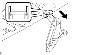
1. REMOVE INNER REAR VIEW MIRROR STAY HOLDER COVER
|
(a) Disengage the 2 claws and slide the inner rear view mirror stay holder cover as shown in the illustration. |
|
|
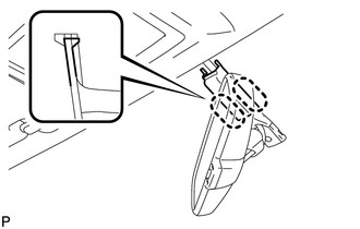
(b) Disengage the 2 claws and remove the inner rear view mirror stay holder cover. |
|
2. REMOVE INNER REAR VIEW MIRROR ASSEMBLY (w/o Automatic High Beam System)
|
(a) Disconnect the connector. |
|
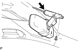
(b) Using a T20 "TORX" socket wrench, remove the screw and the inner rear view mirror assembly.
3. REMOVE INNER REAR VIEW MIRROR ASSEMBLY (w/ Automatic High Beam System)
NOTICE:
- Do not touch of the camera lens (built into the inner rear view mirror assembly) with a bare hand.
- Do not allow anything to adhere to the camera lens (built into the inner rear view mirror assembly).
- Do not apply strong impact to the inner rear view mirror assembly.
- Do not allow any liquids to get on the inner rear view mirror assembly.
|
(a) Disconnect the connector. |
|
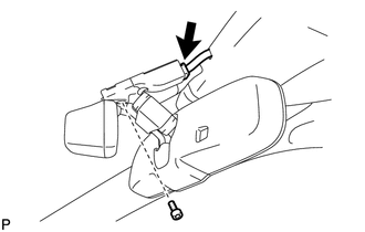
(b) Using a T20 "TORX" socket wrench, remove the screw and the inner rear view mirror assembly.
 Inspection
INSPECTION
PROCEDURE
1. INSPECT INNER REAR VIEW MIRROR ASSEMBLY
(a) Inspect operation of the electrochromic inner mirror.
(1) Connect a positive (+) lead from the battery to terminal 1 and a neg ...
 Installation
INSTALLATION
PROCEDURE
1. INSTALL INNER REAR VIEW MIRROR ASSEMBLY (w/o Automatic High Beam System)
(a) Using a T20 "TORX" socket wrench, install the inner rear view mirror assembly
with ...
Other materials about Toyota Venza:
Diagnosis System
DIAGNOSIS SYSTEM
1. DESCRIPTION
The main body ECU (driver side junction block assembly) and certification ECU
(smart key ECU assembly) control the LIN communication system. LIN communication
system data and Diagnostic Trouble Codes (DTCs) can be read thr ...
Tcm
Components
COMPONENTS
ILLUSTRATION
Removal
REMOVAL
CAUTION / NOTICE / HINT
NOTICE:
If automatic transmission parts are replaced, refer to Parts Replacement Compensation
Table to determine if any additional operations are necessary (See page
). ...
Compressor Lock Sensor Circuit (B1422/22)
SYSTEM DESCRIPTION
The ECM sends the engine speed signal to the A/C amplifier via CAN communication.
The A/C amplifier reads the difference between compressor speed and engine speed.
When the difference becomes too large, the A/C amplifier determines that ...

0.1165