Toyota Venza: Installation
INSTALLATION
PROCEDURE
1. INSTALL INNER REAR VIEW MIRROR ASSEMBLY (w/o Automatic High Beam System)
(a) Using a T20 "TORX" socket wrench, install the inner rear view mirror assembly with the screw.
Torque:
1.5 N·m {15 kgf·cm, 13 in·lbf}
(b) Connect the connector.
2. INSTALL INNER REAR VIEW MIRROR ASSEMBLY (w/ Automatic High Beam System)
NOTICE:
- Do not touch the camera lens (built into the inner rear view mirror assembly) with a bare hand.
- Do not allow anything to adhere to the camera lens (built into the inner rear view mirror assembly).
- Do not apply strong impacts to the inner rear view mirror assembly.
- Do not allow any liquid to get on the inner rear view mirror assembly.
(a) Using a T20 "TORX" socket wrench, install the inner rear view mirror assembly with the screw.
Torque:
1.5 N·m {15 kgf·cm, 13 in·lbf}
(b) Connect the connector.
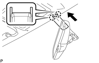
3. INSTALL INNER REAR VIEW MIRROR STAY HOLDER COVER
(a) Engage the 2 claws.
|
(b) Slide the inner rear view mirror stay holder cover and engage the 2 claws and install the cover as shown in the illustration. |
|
 Removal
REMOVAL
PROCEDURE
1. REMOVE INNER REAR VIEW MIRROR STAY HOLDER COVER
(a) Disengage the 2 claws and slide the inner rear view mirror stay holder
cover as shown in the illustration.
...

Other materials about Toyota Venza:
Dtc Check / Clear
DTC CHECK / CLEAR
1. CHECK DTC (When Using Techstream)
(a) Check the DTCs.
(1) Connect the Techstream to the DLC3.
(2) Turn the ignition switch to ON.
(3) Turn the Techstream on.
(4) Read the DTCs following the prompts on the Techstream screen. Enter the ...
Power Source Mode does not Change to ON (IG and ACC)
DESCRIPTION
When the engine switch is pushed with the electrical key in the cabin, the power
management control ECU receives signals to change the power source mode.
HINT:
To allow use of the Techstream to inspect the push-button start function when
the ...
Stop Light Switch
Components
COMPONENTS
ILLUSTRATION
Removal
REMOVAL
PROCEDURE
1. REMOVE STOP LIGHT SWITCH ASSEMBLY
(a) Disconnect the connector.
(b) Turn the stop light switch assembly countercl ...

0.1176