Toyota Venza: Removal
REMOVAL
PROCEDURE
1. REMOVE WHEEL ASSEMBLY
2. REMOVE TIRE PRESSURE WARNING VALVE AND TRANSMITTER
(a) Remove the tire valve cap.
NOTICE:
Keep the removed tire valve cap.
(b) Remove the valve core to release the air from the tire.
NOTICE:
Make sure that a sufficient amount of air has been released.
(c) Remove the nut and washer.
(d) Drop the tire pressure warning valve and transmitter with grommet into the tire.
HINT:
The grommet may remain attached to the rim.
|
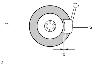
(e) Using a tire remover, remove the tire from the disc wheel. Text in Illustration
NOTICE:
|
|
(f) Take out the tire pressure warning valve and transmitter with grommet from the tire.
(g) Remove the grommet from the tire pressure warning valve and transmitter.
 Components
COMPONENTS
ILLUSTRATION
...
 Installation
INSTALLATION
CAUTION / NOTICE / HINT
NOTICE:
Always use a new grommet and valve core when installing the tire pressure
warning valve and transmitter.
Check that the washer and nut a ...
Other materials about Toyota Venza:
Fail-safe Chart
FAIL-SAFE CHART
If a problem occurs in the power steering system, the power steering assist will
be stopped or the amount of power assist will be decreased to protect the system.
Power Steering System
Malfunction
Fail-safe Operation
...
Registration
REGISTRATION
CAUTION / NOTICE / HINT
HINT:
Register a new recognition code when replacing the door control transmitter
or the door control receiver.
Add mode is used to retain the already registered codes while registering
a new recognit ...
Operation Check
OPERATION CHECK
1. NOTICE WHEN CHECKING THE FOLLOWING
(a) Power door lock/unlock function:
This wireless door lock control function operates only when the following 3 conditions
are met:
(1) There is no key in the ignition key cylinder.
(2) All doors ar ...

0.128