Toyota Venza: Removal
REMOVAL
CAUTION / NOTICE / HINT
NOTICE:
Make sure to select FACE mode before disconnecting the cable from the negative (-) battery terminal.
PROCEDURE
1. RECOVER REFRIGERANT FROM REFRIGERATION SYSTEM
.gif)
2. REMOVE WINDSHIELD WIPER MOTOR AND LINK ASSEMBLY
(See page )
3. REMOVE OUTER COWL TOP PANEL
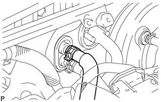
4. DISCONNECT OUTLET HEATER WATER HOSE
|
(a) Using pliers, grip the claws of the clip and slide the clip to disconnect the outlet heater water hose. NOTICE:
|
|
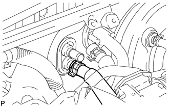
5. DISCONNECT INLET HEATER WATER HOSE
|
(a) Using pliers, grip the claws of the clip and slide the clip to disconnect the inlet heater water hose. NOTICE:
|
|
6. DISCONNECT SUCTION HOSE SUB-ASSEMBLY
|
(a) Remove the bolt, and slide the hook connector. |
|
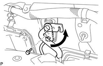
(b) Disconnect the suction hose sub-assembly.
(c) Remove the O-ring from the suction hose sub-assembly.
NOTICE:
Seal the openings of the disconnected parts using vinyl tape to prevent entry of moisture and foreign matter.
7. DISCONNECT AIR CONDITIONING TUBE AND ACCESSORY ASSEMBLY
(a) Disconnect the air conditioning tube and accessory assembly.
(b) Remove the O-ring from the air conditioning tube and accessory assembly.
NOTICE:
Seal the openings of the disconnected parts using vinyl tape to prevent entry of moisture and foreign matter.
8. REMOVE FRONT SEAT ASSEMBLY LH
(See page )
9. REMOVE FRONT SEAT ASSEMBLY RH
(See page )
10. REMOVE INSTRUMENT PANEL SAFETY PAD ASSEMBLY
(See page )
11. REMOVE STEERING POST ASSEMBLY
(See page )
12. REMOVE TURN SIGNAL FLASHER ASSEMBLY
13. REMOVE POWER MANAGEMENT CONTROL ECU
14. REMOVE 4WD CONTROL ECU (for AWD)
15. REMOVE TIRE PRESSURE WARNING ECU
16. REMOVE MAIN BODY ECU (DRIVER SIDE JUNCTION BLOCK ASSEMBLY)
17. REMOVE POWER STEERING ECU ASSEMBLY
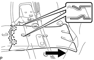
18. REMOVE REAR NO. 2 AIR DUCT
(a) Turn back the floor carpet.
|
(b) Disengage the 4 claws and remove the rear No. 2 air duct as shown in the illustration. |
|
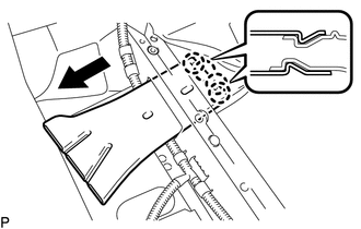
19. REMOVE REAR NO. 1 AIR DUCT
|
(a) Disengage the 2 claws and remove the rear No. 1 air duct. |
|
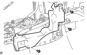
20. REMOVE FLOOR CARPET BRACKET LH
|
(a) Disengage the 2 clamps. |
|
(b) Remove the 3 clips and floor carpet bracket LH.
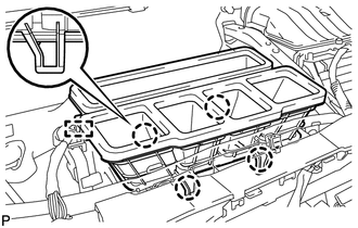
21. REMOVE REAR NO. 4 AIR DUCT
(a) Turn back the floor carpet.
|
(b) Disengage the 4 claws and remove the rear No. 4 air duct as shown in the illustration. |
|
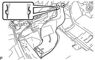
22. REMOVE REAR NO. 3 AIR DUCT
|
(a) Disengage the 2 claws and remove the rear No. 3 air duct. |
|
23. REMOVE FLOOR CARPET BRACKET RH
|
(a) Remove the 3 clips and floor carpet bracket RH. |
|
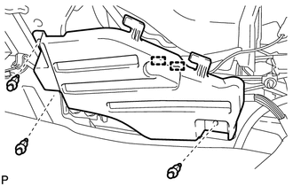
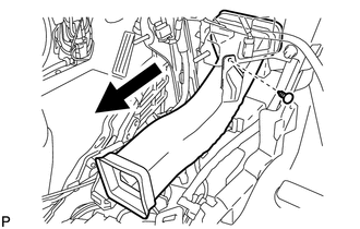
24. REMOVE NO. 1 CONSOLE BOX DUCT
|
(a) Remove the clip and No. 1 console box duct as shown in the illustration. |
|
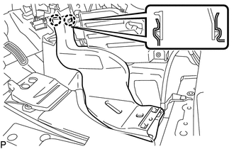
25. REMOVE NO. 6 HEATER TO REGISTER DUCT ASSEMBLY
|
(a) Disengage the clamp. |
|
(b) Disengage the 4 claws and remove the No. 6 heater to register duct assembly.
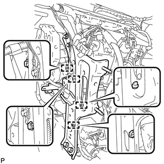
26. REMOVE NO. 3 INSTRUMENT PANEL REINFORCEMENT
|
(a) Disengage the clamp. Text in Illustration
|
|
(b) Remove the bolt and disconnect the earth wire.
(c) Remove the 2 nuts and No. 3 instrument panel reinforcement.
27. REMOVE NO. 1 INSTRUMENT PANEL BRACE SUB-ASSEMBLY
|
(a) Disengage each clamp. |
|
|
(b) Remove the screw. Text in Illustration
|
|
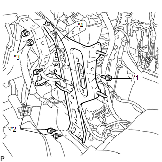
(c) Remove the bolt and disconnect the earth wire.
(d) Remove the 2 bolts, 2 nuts and No. 1 instrument panel brace sub-assembly.
28. REMOVE NO. 2 INSTRUMENT PANEL BRACE SUB-ASSEMBLY
|
(a) Disengage each clamp. Text in Illustration
|
|
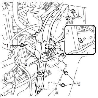
(b) Remove the screw.
(c) Remove the bolt and disconnect the earth wire.
(d) Remove the bolt, 2 nuts and No. 2 instrument panel brace sub-assembly.
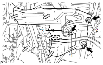
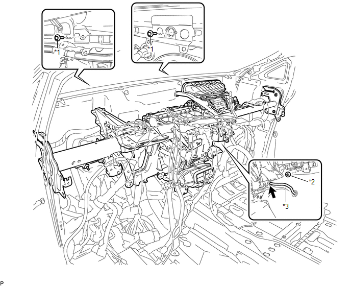
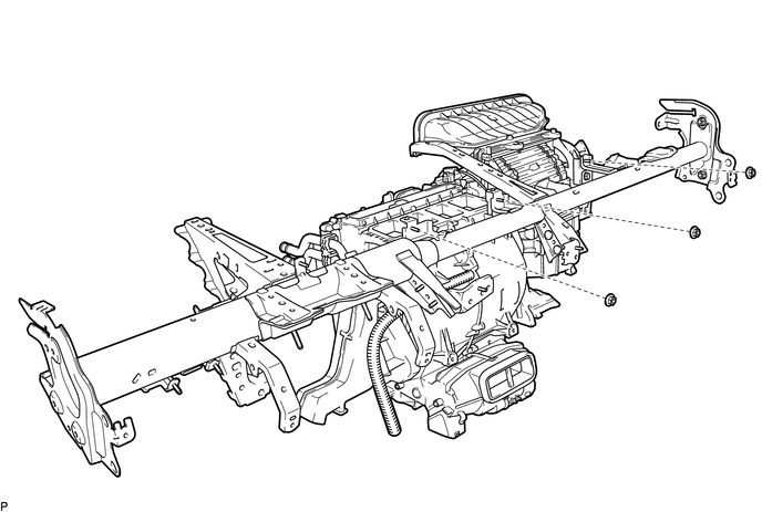
29. REMOVE INSTRUMENT PANEL REINFORCEMENT ASSEMBLY WITH AIR CONDITIONING UNIT ASSEMBLY
(a) Remove the bolt, 2 nuts and screw.
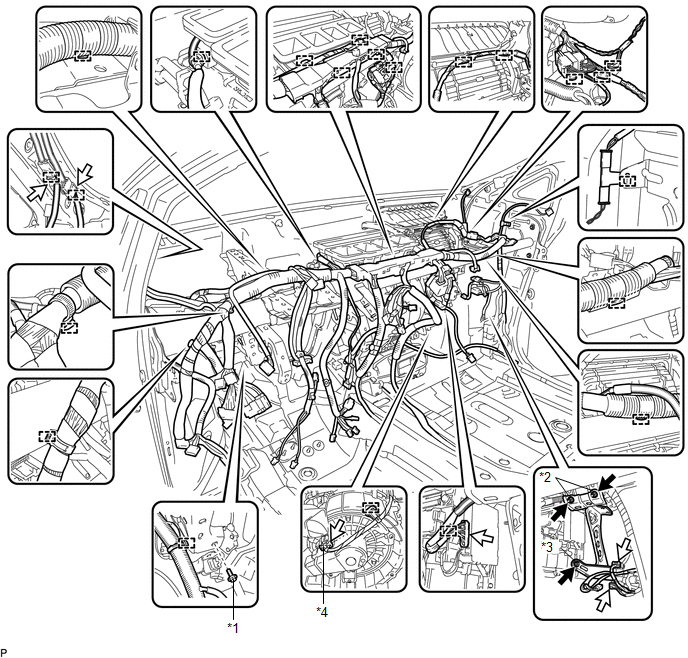 Text in Illustration
|
*1 |
Bolt |
*2 |
Nut |
|
*3 |
Screw |
*4 |
Blower Motor Connector |
(b) Disconnect the blower motor connector.
(c) Disconnect each connector.
(d) Disengage each clamp.
(e) Remove the 2 bolts from the engine compartment side.
 Text in Illustration
|
*1 |
Bolt |
*2 |
Nut |
|
*3 |
Cooler Drain Hose |
- |
- |
(f) Remove the nut.
(g) Disconnect the cooler drain hose.
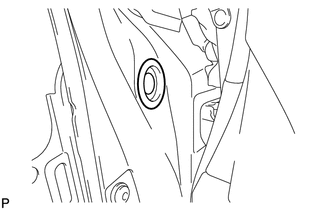
(h) for LH side:
|
(1) Remove the hole plug. |
|
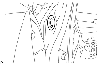
(i) for RH side:
|
(1) Remove the hole plug. |
|
(j) Using a T40 "TORX" socket wrench, remove the 4 "TORX" bolts.
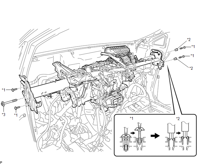 Text in Illustration
|
*1 |
"TORX" Bolt |
*2 |
Collar |
|
*3 |
Bolt |
- |
- |
HINT:
The "TORX" bolts on the passenger side may be removed with the collars for adjustment.
(k) Using a 12 mm hexagon wrench, remove the 2 collars.
(l) Remove the bolt and the instrument panel reinforcement assembly with air conditioning unit assembly.
30. REMOVE AIR CONDITIONING UNIT ASSEMBLY
(a) Remove the 3 nuts and air conditioning unit assembly from the instrument panel reinforcement assembly.
 Components
COMPONENTS
ILLUSTRATION
ILLUSTRATION
ILLUSTRATION
ILLUSTRATION
ILLUSTRATION
ILLUSTRATION
ILLUSTRATION
...
 Disassembly
DISASSEMBLY
PROCEDURE
1. REMOVE TRANSPONDER KEY ECU ASSEMBLY (w/ Engine Immobiliser System)
2. REMOVE NO. 1 FINISH PANEL MOUNTING BRACKET
(a) Remove the 2 bolts and 2 No. 1 finish pa ...
Other materials about Toyota Venza:
System Diagram
SYSTEM DIAGRAM
Communication Table
Transmitting ECU (Transmitter)
Receiving ECU (Receiver)
Signal
Line
Certification ECU
(Smart key ECU assembly)
Main body ECU
(Driver side junc ...
Installation
INSTALLATION
PROCEDURE
1. INSTALL PARKING BRAKE PEDAL ASSEMBLY
(a) Install the parking brake pedal assembly with the 3 nuts.
Torque:
21 N·m {214 kgf·cm, 15 ft·lbf}
(b) Connect t ...
Front Occupant Classification Sensor RH Collision Detection (B1786)
DESCRIPTION
DTC B1786 is output when the occupant classification ECU receives a collision
detection signal sent by the front occupant classification sensor RH if an accident
occurs.
DTC B1786 is also output when the front seat assembly RH is subjected to ...

0.1241