Toyota Venza: Front Occupant Classification Sensor RH Collision Detection (B1786)
DESCRIPTION
DTC B1786 is output when the occupant classification ECU receives a collision detection signal sent by the front occupant classification sensor RH if an accident occurs.
DTC B1786 is also output when the front seat assembly RH is subjected to a strong impact, even if an actual accident does not occur.
However, when the occupant classification ECU outputs a collision detection signal, even if the vehicle is not in a collision, DTC B1786 can be cleared by Zero Point Calibration and Sensitivity Check.
Therefore, if DTC B1786 is output, first perform Zero Point Calibration and Sensitivity Check.
|
DTC No. |
DTC Detection Condition |
Trouble Area |
|---|---|---|
|
B1786 |
|
|
HINT:
When DTC B1650/32 is detected as a result of troubleshooting for the airbag system, check the DTCs stored in the occupant classification ECU. When DTC B1786 is output, perform troubleshooting for the DTC.
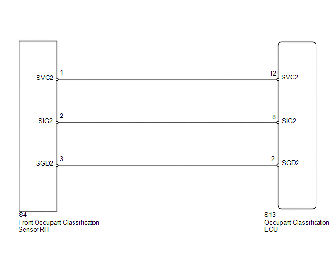
WIRING DIAGRAM
PROCEDURE
|
1. |
PERFORM ZERO POINT CALIBRATION |
(a) Connect the Techstream to the DLC3.
(b) Turn the ignition switch to ON.
(c) Using the Techstream, perform Zero Point Calibration (See page
.gif) ).
).
OK:
"Zero Point Calibration is complete." is displayed.
| NG | .gif) |
GO TO STEP 4 |
|
.gif)
|
2. |
PERFORM SENSITIVITY CHECK |
(a) Using the Techstream, perform Sensitivity Check (See page
).
Standard:
27 to 33 kg (59.5 to 72.8 lb)
| NG | |
GO TO STEP 4 |
|
|
3. |
CHECK DTC |
(a) Turn the ignition switch to ON.
(b) Clear the DTCs stored in the occupant classification ECU (See page
).
(c) Clear the DTCs stored in the center airbag sensor assembly (See page
).
(d) Turn the ignition switch off.
(e) Turn the ignition switch to ON.
(f) Check for DTCs (See page ).
OK:
DTC B1786 is not output.
HINT:
Codes other than DTC B1786 may be output at this time, but they are not related to this check.
| OK | |
END |
|
|
4. |
REPLACE FRONT SEAT FRAME WITH ADJUSTER ASSEMBLY RH |
(a) Turn the ignition switch off.
(b) Disconnect the cable from the negative (-) battery terminal.
(c) Replace the front seat frame with adjuster assembly RH (See page
for power seat or
for manual seat).
HINT:
Perform the inspection using parts from a normal vehicle if possible.
|
|
5. |
PERFORM ZERO POINT CALIBRATION |
(a) Connect the cable to the negative (-) battery terminal.
(b) Connect the Techstream to the DLC3.
(c) Turn the ignition switch to ON.
(d) Using the Techstream, perform Zero Point Calibration (See page
).
OK:
"Zero Point Calibration is complete." is displayed.
| NG | |
GO TO STEP 8 |
|
|
6. |
PERFORM SENSITIVITY CHECK |
(a) Using the Techstream, perform Sensitivity Check (See page
).
Standard:
27 to 33 kg (59.5 to 72.8 lb)
| NG | |
GO TO STEP 8 |
|
|
7. |
CHECK DTC |
(a) Turn the ignition switch to ON.
(b) Clear the DTCs stored in the occupant classification ECU (See page
).
(c) Clear the DTCs stored in the center airbag sensor assembly (See page
).
(d) Turn the ignition switch off.
(e) Turn the ignition switch to ON.
(f) Check for DTCs (See page ).
OK:
DTC B1786 is not output.
HINT:
Codes other than DTC B1786 may be output at this time, but they are not related to this check.
| OK | |
END |
|
|
8. |
REPLACE OCCUPANT CLASSIFICATION ECU |
(a) Turn the ignition switch off.
(b) Disconnect the cable from the negative (-) battery terminal.
(c) Replace the occupant classification ECU (See page
).
|
|
9. |
PERFORM ZERO POINT CALIBRATION |
(a) Connect the cable to the negative (-) battery terminal.
(b) Connect the Techstream to the DLC3.
(c) Turn the ignition switch to ON.
(d) Using the Techstream, perform Zero Point Calibration (See page
).
OK:
"Zero Point Calibration is complete." is displayed.
|
|
10. |
PERFORM SENSITIVITY CHECK |
(a) Using the Techstream, perform Sensitivity Check (See page
).
Standard:
27 to 33 kg (59.5 to 72.8 lb)
| NEXT | |
END |
 Rear Occupant Classification Sensor RH Collision Detection (B1788)
DESCRIPTION
DTC B1788 is output when the occupant classification ECU receives a collision
detection signal sent by the rear occupant classification sensor RH if an accident
occurs.
DTC B1788 is ...
 Front Occupant Classification Sensor LH Collision Detection (B1785)
DESCRIPTION
DTC B1785 is output when the occupant classification ECU receives a collision
detection signal sent by the front occupant classification sensor LH if an accident
occurs.
DTC B1785 is ...
Other materials about Toyota Venza:
Power Mirror Control System(w/o Memory)
Parts Location
PARTS LOCATION
ILLUSTRATION
Problem Symptoms Table
PROBLEM SYMPTOMS TABLE
HINT:
Use the table below to help determine the cause of problem symptoms. If multiple
suspected areas are listed, the potential causes of the symptoms are l ...
Engine (ignition) switch (vehicles without smart key system)
- Starting the engine
Check that the parking brake is
set.
Check that the shift lever is set
in “P”.
Sit in the driver’s seat and firmly
depress the brake pedal.
Turn the engine switch to the “START”
position and start the engine ...
Vehicle Speed Sensor "A" (P0500)
DESCRIPTION
The speed sensors detect the wheel speed and send the appropriate signals to
the skid control ECU. The skid control ECU converts these wheel speed signals into
a 4-pulse signal and outputs it to the TCM via the combination meter. The TCM deter ...

0.1313