Toyota Venza: System Diagram
SYSTEM DIAGRAM
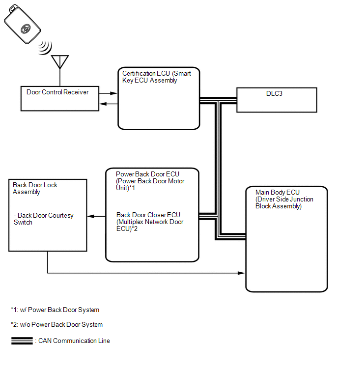
 Communication Table
|
Transmitting ECU (Transmitter) |
Receiving ECU (Receiver) |
Signal |
Line |
|---|---|---|---|
|
Certification ECU (Smart key ECU assembly) |
Main body ECU (Driver side junction block assembly) |
Wireless door lock signal |
CAN |
|
Main body ECU (Driver side junction block assembly) |
Power Back Door ECU (Power Back door motor unit)*1 Back Door Closer ECU (Multiplex Network Door ECU)*2 |
Power Back door control signal |
CAN |
- *1: w/ Power Back Door System
- *2: w/o Power Back Door System
 System Description
SYSTEM DESCRIPTION
1. WIRELESS DOOR LOCK CONTROL SYSTEM
The wireless door lock control system can be used to lock and unlock all doors
from a distance. The system is controlled by a door control t ...
 How To Proceed With Troubleshooting
CAUTION / NOTICE / HINT
HINT:
The wireless door lock control system troubleshooting procedures are
based on the premise that the power door lock control system is operating
normally. ...
Other materials about Toyota Venza:
TC and CG Terminal Circuit
DESCRIPTION
Connecting terminals TC and CG of the DLC3 causes the ECU to display the DTC
by blinking the ABS warning and slip indicator lights.
WIRING DIAGRAM
CAUTION / NOTICE / HINT
HINT:
When the warning lights continue to blink, a ground short in t ...
Fuel Pump Control Circuit
DESCRIPTION
1. w/o Smart Key System
When the engine is cranked, the starter relay drive signal output from the ignition
switch is input into the STA terminal of the ECM, and the NE signal generated by
the crankshaft position sensor is also input into the ...
Precaution
PRECAUTION
NOTICE:
When disconnecting the cable from the negative (-) battery terminal, initialize
the following systems after the cable is reconnected.
System Name
See Procedure
Back Door Closer System
...

0.1634