Toyota Venza: Installation
INSTALLATION
PROCEDURE
1. INSTALL PARKING BRAKE PEDAL ASSEMBLY
|
(a) Install the parking brake pedal assembly with the 3 nuts. Torque: 21 N·m {214 kgf·cm, 15 ft·lbf} |
|
.png)
|
(b) Connect the parking brake switch connector. |
|
.png)
(c) Install the No. 1 parking brake cable assembly with the nut and 4 bolts.
.png)
Torque:
Nut :
5.4 N·m {55 kgf·cm, 48 in·lbf}
Bolt :
15 N·m {153 kgf·cm, 11 ft·lbf}
|
(d) Temporarily install the No. 1 wire adjusting nut and lock nut. Text in Illustration
HINT: After adjusting parking brake pedal travel, tighten the lock nut. |
|
.png)
|
(e) Engage the 4 clamps to install the wire harness. |
|
.png)
|
(f) Connect the 2 connectors. |
|
.png)
|
(g) Connect the heated oxygen sensor connector and engage the 2 clamps (for 2GR-FE). |
|
.png)
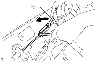
2. CONNECT NO. 4 PARKING BRAKE CABLE ASSEMBLY
|
(a) Holding the lock nut of the No. 1 parking brake cable assembly, tighten the turnbuckle of the No. 4 parking brake cable assembly to connect the No. 4 parking brake cable assembly to the No. 1 parking brake cable assembly. Text in Illustration
Torque: 5.4 N·m {55 kgf·cm, 48 in·lbf} |
|
3. INSTALL FRONT NO. 2 FLOOR SILENCER
|
(a) Install the front No. 2 floor silencer. |
|
.png)
4. INSTALL REAR NO. 1 AIR DUCT
.gif)
5. INSTALL REAR NO. 2 AIR DUCT
6. INSTALL YAW RATE AND ACCELERATION SENSOR
HINT:
Refer to the instructions for Installation of the yaw rate and acceleration sensor
(See page ).
7. ADJUST PARKING BRAKE SHOE CLEARANCE AND PARKING BRAKE PEDAL TRAVEL
8. INSPECT BRAKE WARNING LIGHT
 Reassembly
REASSEMBLY
PROCEDURE
1. INSTALL PARKING PEDAL PAD
(a) Install the parking pedal pad to the parking brake pedal assembly.
2. INSTALL PARKING BRAKE SWITCH ASSEMBLY
3. INSTALL NO. 1 PARKING BRAKE ...

Other materials about Toyota Venza:
VSC OFF Indicator Light does not Come ON
DESCRIPTION
The skid control ECU is connected to the combination meter via CAN communication.
WIRING DIAGRAM
Refer to VSC OFF Indicator Light Remains ON (See page
).
PROCEDURE
1.
CHECK CAN COMMUNICATION SYSTEM
(a) Check ...
Fail-safe Chart
FAIL-SAFE CHART
1. FAIL-SAFE FUNCTION
If the following malfunctions occur, the AWD control ECU will stop the
function of 4WD control system or partly change the function to control
the system.
If a malfunction occurs in the senso ...
Removal
REMOVAL
PROCEDURE
1. DISCHARGE FUEL SYSTEM PRESSURE
HINT:
See page
2. DISCONNECT CABLE FROM NEGATIVE BATTERY TERMINAL
NOTICE:
When disconnecting the cable, some systems need to be initialized after the cable
is reconnected (See page ).
3. REMOVE W ...

0.1731