Toyota Venza: Components
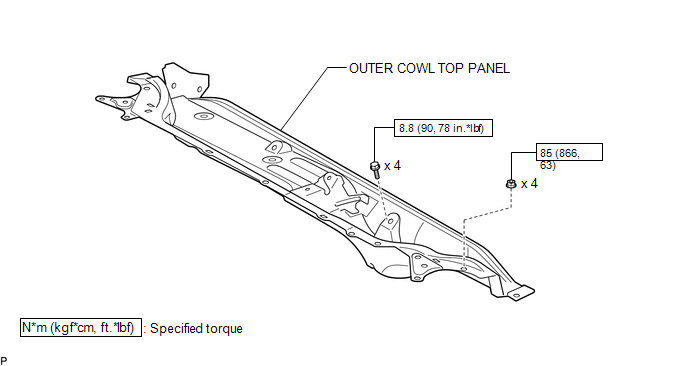
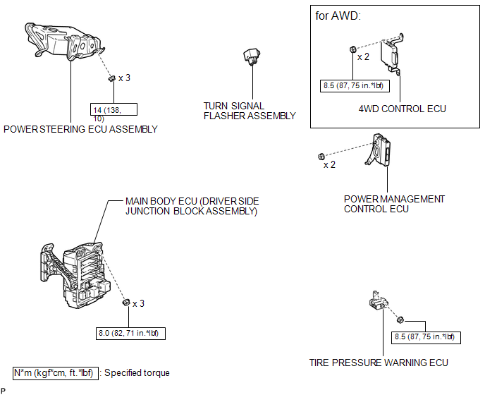
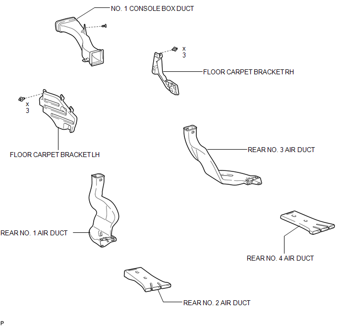
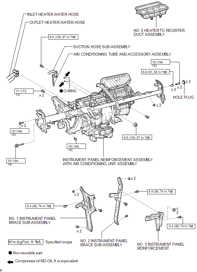
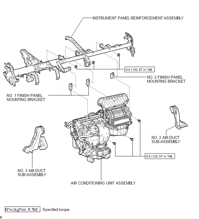
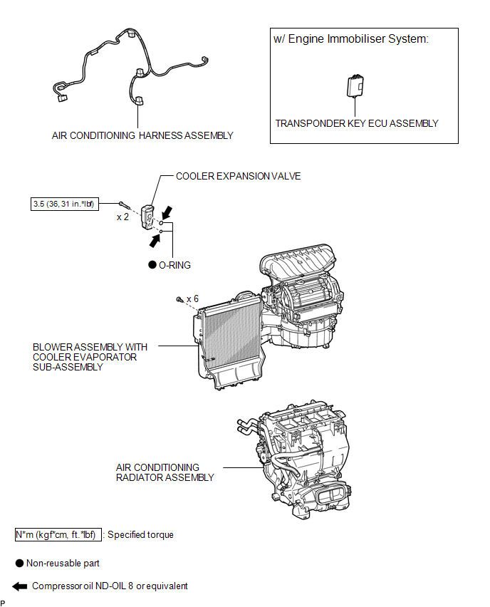
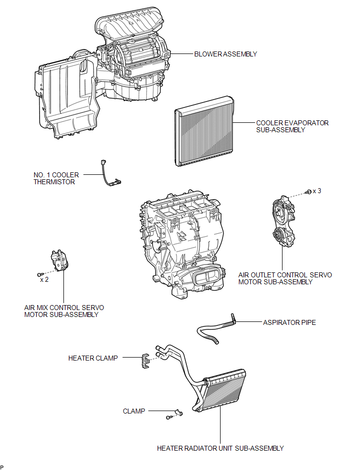
COMPONENTS
ILLUSTRATION
ILLUSTRATION
ILLUSTRATION
ILLUSTRATION
ILLUSTRATION
ILLUSTRATION
ILLUSTRATION

 Removal
REMOVAL
CAUTION / NOTICE / HINT
NOTICE:
Make sure to select FACE mode before disconnecting the cable from the negative
(-) battery terminal.
PROCEDURE
1. RECOVER REFRIGERANT FROM REFRIGERATION ...
Other materials about Toyota Venza:
Check CAN Bus Lines for Short Circuit
DESCRIPTION
There may be a short circuit in the CAN bus main wire and/or CAN branch wire
when the resistance between terminals 6 (CANH) and 14 (CANL) of the DLC3 is below
54 Ω.
Symptom
Trouble Area
Resistance betwe ...
System Description
SYSTEM DESCRIPTION
1. WIRELESS DOOR LOCK CONTROL SYSTEM
The wireless door lock control system functions to lock and unlock all the doors
from a distance. The system is controlled by a door control transmitter which sends
radio waves to the door control r ...
SFR Solenoid Circuit (C0226/21,C0236/22,C0246/23,C0256/24,C1225/25-C1228/28)
DESCRIPTION
These solenoids turn on when signals are received from the skid control ECU and
they control the pressure acting on the wheel cylinders to control the braking force.
DTC Code
DTC Detection Condition
Trouble Area ...

0.1272