Toyota Venza: Installation
INSTALLATION
PROCEDURE
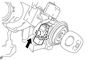
1. INSTALL UNLOCK WARNING SWITCH
|
(a) Engage the 2 claws and install the unlock warning switch to the steering column upper bracket. |
|
(b) Extract the key.
|
(c) Connect the connector. |
|
.png)
2. INSTALL TURN SIGNAL SWITCH ASSEMBLY WITH SPIRAL CABLE SUB-ASSEMBLY
.gif)
3. INSTALL UPPER STEERING COLUMN COVER
4. INSTALL LOWER STEERING COLUMN COVER
5. ALIGN FRONT WHEELS FACING STRAIGHT AHEAD
6. ADJUST SPIRAL CABLE
7. INSTALL STEERING WHEEL ASSEMBLY
8. INSTALL STEERING PAD
9. INSTALL LOWER NO. 3 STEERING WHEEL COVER
10. INSTALL LOWER NO. 2 STEERING WHEEL COVER
11. INSPECT STEERING WHEEL CENTER POINT
12. CONNECT CABLE TO NEGATIVE BATTERY TERMINAL
NOTICE:
When disconnecting the cable, some systems need to be initialized after the cable
is reconnected (See page ).
13. INSPECT STEERING PAD
14. INSPECT SRS WARNING LIGHT
(See page )
 Removal
REMOVAL
PROCEDURE
1. ALIGN FRONT WHEELS FACING STRAIGHT AHEAD
2. DISCONNECT CABLE FROM NEGATIVE BATTERY TERMINAL
CAUTION:
Wait at least 90 seconds after disconnecting the cable from the negative ...
 Wireless Door Lock Buzzer
Components
COMPONENTS
ILLUSTRATION
Installation
INSTALLATION
PROCEDURE
1. INSTALL WIRELESS DOOR LOCK BUZZER
(a) Engage the clamp and install the wireless door lock buzzer.
...
Other materials about Toyota Venza:
Disassembly
DISASSEMBLY
PROCEDURE
1. DISCONNECT CABLE FROM NEGATIVE BATTERY TERMINAL
NOTICE:
When disconnecting the cable, some systems need to be initialized after the cable
is reconnected (See page ).
2. REMOVE REAR DOOR INSIDE HANDLE BEZEL PLUG
(a) ...
Diagnostic Trouble Code Chart
DIAGNOSTIC TROUBLE CODE CHART
HINT:
When the air conditioning system functions properly, DTC B1400/00 is output.
Air Conditioning System
DTC Code
Detection Item
Trouble Area
Memory*3
See page
...
Receiver Error (C2176/76)
DESCRIPTION
The signals are transmitted to the tire pressure warning antenna and receiver
on the body as radio waves and then sent to the tire pressure warning ECU.
DTC No.
DTC Detection Condition
Trouble Area
...

0.1772