Toyota Venza: Removal
REMOVAL
PROCEDURE
1. REMOVE FRONT DOOR SCUFF PLATE LH
.gif)
2. REMOVE COWL SIDE TRIM SUB-ASSEMBLY LH
3. REMOVE LOWER NO. 1 INSTRUMENT PANEL FINISH PANEL
4. REMOVE LOWER STEERING COLUMN COVER
|
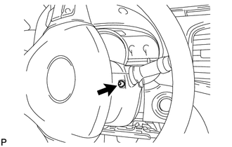
(a) Turn the steering wheel assembly to the right and remove the screw shown in the illustration. |
|
|
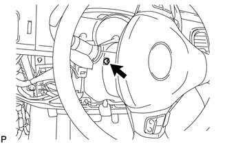
(b) Turn the steering wheel assembly to the left and remove the screw shown in the illustration. |
|
|
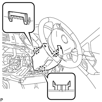
(c) Disengage the 3 claws and remove the lower steering column cover. |
|
5. REMOVE UPPER STEERING COLUMN COVER
|
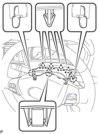
(a) Disengage the 4 clips and 3 claws and remove the upper steering column cover. |
|
6. REMOVE WINDSHIELD WIPER SWITCH ASSEMBLY
|
(a) Disconnect the 2 connectors. |
|
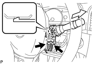
(b) Disengage the claw and remove the windshield wiper switch assembly as shown in the illustration.
NOTICE:
If the claw is pushed with excessive force, it may break.
 Components
COMPONENTS
ILLUSTRATION
...
 Inspection
INSPECTION
PROCEDURE
1. INSPECT WINDSHIELD WIPER SWITCH ASSEMBLY
(a) Measure the resistance according to the value(s) in the table below.
Standard Resistance:
Front Wiper Switch
...
Other materials about Toyota Venza:
Communication Malfunction No. 1 (B2797)
DESCRIPTION
This DTC is stored when an error occurs in communication between the transponder
key amplifier and the transponder key ECU assembly.
HINT:
Some noise is found in the communication line.
DTC No.
DTC Detection Condition
...
Installation
INSTALLATION
PROCEDURE
1. INSTALL REAR DOOR COURTESY LIGHT SWITCH
(a) Using "TORX" socket wrench T30, install the rear door courtesy light
switch with the "TORX" bolt.
Torque:
8.0 N·m {82 kgf·cm, 71 in·lbf}
...
Precaution
PRECAUTION
1. PRECAUTION FOR DISCONNECTING BATTERY CABLE
NOTICE:
When disconnecting the cable from the negative (-) battery terminal, initialize
the following systems after the cable is reconnected.
System
See Procedure
...

0.1448