Toyota Venza: Rear Window Defogger System does not Operate
DESCRIPTION
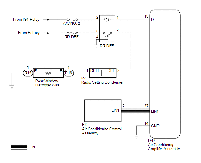
When the rear window defogger switch on the air conditioning control assembly is pressed, the operation signal is transmitted to the air conditioning amplifier assembly through the LIN communication line. When the air conditioning amplifier assembly receives the signal, it turns on the RR DEF relay to operate the rear window defogger.
WIRING DIAGRAM
CAUTION / NOTICE / HINT
NOTICE:
Inspect the fuses for circuits related to this system before performing the following inspection procedure.
PROCEDURE
|
1. |
CHECK AIR CONDITIONING SYSTEM |
(a) Check the air conditioning system.
HINT:
Both the window defogger system operation signal and air conditioning system operation signal are transmitted to the air conditioning amplifier assembly through the same LIN communication line.
Result|
Result |
Proceed to |
|---|---|
|
The air conditioning system operates normally. |
A |
|
The air conditioning system does not operate normally. |
B |
| B | .gif) |
GO TO AIR CONDITIONING SYSTEM |
|
.gif)
|
2. |
PERFORM ACTIVE TEST USING TECHSTREAM |
(a) Connect the Techstream to the DLC3.
(b) Turn the ignition switch to ON.
(c) Turn the Techstream on.
(d) Enter the following menus: Body Electrical / Air Conditioner / Active Test.
(e) Perform the Active Test according to the display on the Techstream.
Air Conditioner|
Tester Display |
Test Part |
Control Range |
Diagnostic Note |
|---|---|---|---|
|
Defogger Relay (Rear) |
Rear window defogger |
OFF or ON |
- |
OK:
The window defogger system operates normally.
| OK | |
REPLACE AIR CONDITIONING CONTROL ASSEMBLY |
|
|
3. |
INSPECT RR DEF RELAY |
|
(a) Remove the RR DEF relay from the engine room relay block. |
|
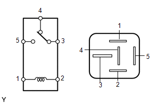
(b) Measure the resistance according to the value(s) in the table below.
Standard Resistance:
|
Tester Connection |
Condition |
Specified Condition |
|---|---|---|
|
3 - 4 |
Battery voltage applied between terminals 1 and 2 |
10 kΩ or higher |
|
3 - 4 |
Battery voltage not applied between terminals 1 and 2 |
Below 1 Ω |
|
3 - 5 |
Battery voltage applied between terminals 1 and 2 |
Below 1 Ω |
|
3 - 5 |
Battery voltage not applied between terminals 1 and 2 |
10 kΩ or higher |
| NG | |
REPLACE RR DEF RELAY |
|
|
4. |
CHECK HARNESS AND CONNECTOR (DEF RELAY POWER SOURCE) |
|
(a) Measure the voltage according to the value(s) in the table below. Standard Voltage:
|
|
| NG | |
REPAIR OR REPLACE HARNESS OR CONNECTOR |
|
|
5. |
CHECK HARNESS AND CONNECTOR (RR DEF RELAY - AIR CONDITIONING AMPLIFIER ASSEMBLY) |
|
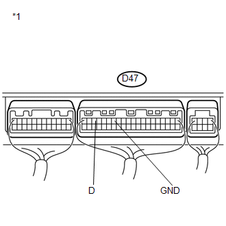
(a) Disconnect the D47 air conditioning amplifier assembly connector. |
|
(b) Measure the resistance according to the value(s) in the table below.
Standard Resistance:
|
Tester Connection |
Condition |
Specified Condition |
|---|---|---|
|
Engine room relay block RR DEF relay terminal 1 - D47-18 (D) |
Always |
Below 1 Ω |
|
D47-14 (GND) - Body ground |
Always |
Below 1 Ω |
|
D47-18 (D) - Body ground |
Always |
10 kΩ or higher |
|
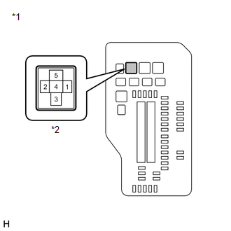
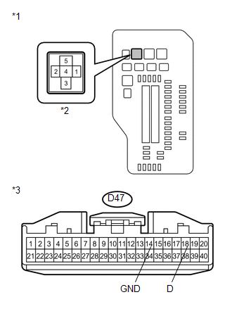
*1 |
Engine Room Relay Block |
|
*2 |
RR DEF Relay Terminal |
|
*3 |
Front view of wire harness connector (to Air Conditioning Amplifier Assembly) |
| NG | |
REPAIR OR REPLACE HARNESS OR CONNECTOR |
|
|
6. |
INSPECT AIR CONDITIONING AMPLIFIER ASSEMBLY |
|
(a) Install the RR DEF relay to the engine room relay block. |
|
(b) Reconnect the D47 air conditioning amplifier assembly connector.
(c) Measure the voltage according to the value(s) in the table below.
Standard Voltage:
|
Tester Connection |
Condition |
Specified Condition |
|---|---|---|
|
D47-18 (D) - D47-14 (GND) |
Ignition switch ON, rear window defogger switch off |
11 to 14 V |
|
D47-18 (D) - D47-14 (GND) |
Ignition switch ON, rear window defogger switch on |
Below 1 V |
|
*1 |
Component with harness connected (Air Conditioning Amplifier Assembly) |
| NG | |
REPLACE AIR CONDITIONING AMPLIFIER ASSEMBLY |
|
|
7. |
CHECK HARNESS AND CONNECTOR (RR DEF RELAY POWER SOURCE) |
|
(a) Remove the RR DEF relay from the engine room relay block. |
|
(b) Measure the voltage according to the value(s) in the table below.
Standard Voltage:
|
Tester Connection |
Condition |
Specified Condition |
|---|---|---|
|
Engine room relay block RR DEF relay terminal 5 - Body ground |
Always |
11 to 14 V |
|
*1 |
Engine Room Relay Block |
|
*2 |
RR DEF Relay Terminal |
| NG | |
REPAIR OR REPLACE HARNESS OR CONNECTOR |
|
|
8. |
CHECK HARNESS AND CONNECTOR (RR DEF RELAY - RADIO SETTING CONDENSER) |
|
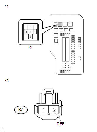
(a) Disconnect the R7 radio setting condenser connectors. |
|
(b) Measure the resistance according to the value(s) in the table below.
Standard Resistance:
|
Tester Connection |
Condition |
Specified Condition |
|---|---|---|
|
R7-2 (DEF) - Engine room relay block RR DEF relay terminal 3 |
Always |
Below 1 Ω |
|
R7-2 (DEF) - Body ground |
Always |
10 kΩ or higher |
|
Engine room relay block RR DEF relay terminal 3 - Body ground |
Always |
10 kΩ or higher |
|
*1 |
Engine Room Relay Block |
|
*2 |
RR DEF Relay Terminal |
|
*3 |
Front view of wire harness connector (to Radio Setting Condenser) |
| NG | |
REPAIR OR REPLACE HARNESS OR CONNECTOR |
|
|
9. |
CHECK HARNESS AND CONNECTOR (RADIO SETTING CONDENSER - REAR WINDOW DEFOGGER) |
(a) Disconnect the R16 rear window defogger connector.
(b) Measure the resistance according to the value(s) in the table below.
Standard Resistance:
|
Tester Connection |
Condition |
Specified Condition |
|---|---|---|
|
R7-1 (DEFB) - R16-1 (B) |
Always |
Below 1 Ω |
|
R7-1 (DEFB) - Body ground |
Always |
10 kΩ or higher |
| NG | |
REPAIR OR REPLACE HARNESS OR CONNECTOR |
|
|
10. |
INSPECT BACK DOOR GLASS (REAR WINDOW DEFOGGER WIRE) |
|
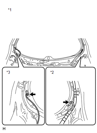
(a) Disconnect the R15 rear window defogger connector. |
|
(b) Measure the resistance according to the value(s) in the table below.
Standard Resistance:
|
Tester Connection |
Condition |
Specified Condition |
|---|---|---|
|
1 - 1 |
Always |
Below 1 Ω |
|
*1 |
Component without harness connected (Back Door Glass (Rear Window Defogger Wire)) |
|
*2 |
Battery Side |
|
*3 |
Body Ground Side |
| NG | |
REPLACE BACK DOOR GLASS (REAR WINDOW DEFOGGER WIRE) |
|
|
11. |
CHECK HARNESS AND CONNECTOR (REAR WINDOW DEFOGGER - BODY GROUND) |
(a) Measure the resistance according to the value(s) in the table below.
Standard Resistance:
|
Tester Connection |
Condition |
Specified Condition |
|---|---|---|
|
R15-1 - Body ground |
Always |
Below 1 Ω |
| NG | |
REPAIR OR REPLACE HARNESS OR CONNECTOR |
|
|
12. |
REPLACE RADIO SETTING CONDENSER |
(a) Replace the radio setting condenser.
|
|
13. |
CHECK REAR WINDOW DEFOGGER SYSTEM |
(a) Turn the ignition switch to ON, press the rear window defogger switch, and
check that the window defogger operates (See page
.gif) ).
).
|
Result |
Proceed to |
|---|---|
|
The window defogger system operates normally |
A |
|
The window defogger system operate does not normally |
B |
| A | |
END |
| B | |
REPLACE AIR CONDITIONING AMPLIFIER ASSEMBLY |
 Diagnosis System
DIAGNOSIS SYSTEM
1. CHECK DLC3
(a) Check the DLC3 (See page ).
2. INSPECT BATTERY VOLTAGE
(a) Measure the battery voltage.
Standard Voltage:
11 to 14 V
If the voltage is below 11 V, recharge ...
 Window Defogger Wire
On-vehicle Inspection
ON-VEHICLE INSPECTION
PROCEDURE
1. CHECK REAR WINDOW DEFOGGER SYSTEM OPERATION
(a) When the ignition switch is turned to ON and the rear window defogger switch
is pressed ...
Other materials about Toyota Venza:
Stereo Component Amplifier Malfunction (B15A3)
DESCRIPTION
This DTC is stored when a malfunction occurs in the stereo component amplifier
assembly.
DTC No.
DTC Detection Condition
Trouble Area
B15A3
When any of the following conditions is met ...
Blind Spot Mirrors
The Blind Spot Mirrors increase the view of surrounding area to assist the driver
when checking surrounding area before changing lanes.
1. Blind Spot Mirror field of view
2. Main mirror field of view
- Mirror angle can be adjusted when
►V ...
Installation
INSTALLATION
PROCEDURE
1. INSTALL FUEL SUCTION TUBE ASSEMBLY WITH PUMP AND GAUGE
(a) Install a new fuel suction tube set gasket onto the fuel tank.
(b) Connect the fuel tube with the clip.
(c) Set ...

0.1276