Toyota Venza: Inspection
INSPECTION
PROCEDURE
1. INSPECT WINDSHIELD WIPER SWITCH ASSEMBLY
|
(a) Measure the resistance according to the value(s) in the table below. Standard Resistance: Front Wiper Switch
Front Washer Switch
Rear Wiper Switch
Rear Washer Switch
If the result is not as specified, replace the windshield wiper switch assembly. Text in Illustration
|
|
(b) Check the intermittent operation.
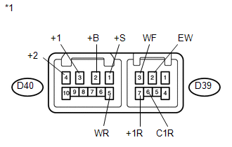
(1) Connect a voltmeter positive (+) lead to terminal D40-3 (+1) and a negative (-) lead to terminal D39-2 (EW).
(2) Connect a battery positive (+) lead to terminal D40-2 (+B) and a negative (-) lead to terminal D39-2 (EW) and D40-1 (+S).
(3) Turn the wiper switch to the INT position.
(4) Connect a battery positive (+) lead to terminal D40-1 (+S) for 5 seconds.
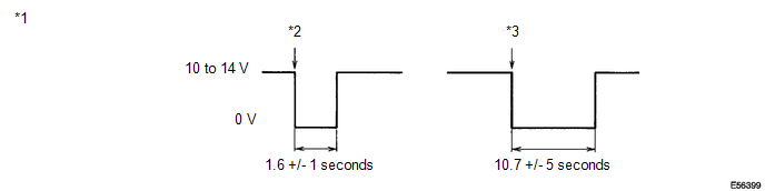
(5) Connect a battery negative (-) lead to terminal D40-1 (+S). Operate the intermittent wiper relay and check the voltage between terminals D40-3 (+1) and D39-2 (EW).
OK:
Voltage changes as shown in the illustration.
If the result is not as specified, replace the windshield wiper switch assembly.
Text in Illustration|
*1 |
Voltage between terminals D40-3 (+1) and D39-2 (EW) |
*2 |
FAST: Connect battery negative lead to terminal D40-1 (+S) |
|
*3 |
SLOW: Connect battery negative lead to terminal D40-1 (+S) |
- |
- |
 Removal
REMOVAL
PROCEDURE
1. REMOVE FRONT DOOR SCUFF PLATE LH
2. REMOVE COWL SIDE TRIM SUB-ASSEMBLY LH
3. REMOVE LOWER NO. 1 INSTRUMENT PANEL FINISH PANEL
4. REMOVE LOWER STEERING COLUMN COVER
...
 Installation
INSTALLATION
PROCEDURE
1. INSTALL WINDSHIELD WIPER SWITCH ASSEMBLY
(a) Engage the claw to install the windshield wiper switch assembly as
shown in the illustration.
...
Other materials about Toyota Venza:
Clearance Warning Buzzer
Components
COMPONENTS
ILLUSTRATION
Removal
REMOVAL
PROCEDURE
1. REMOVE FRONT DOOR SCUFF PLATE LH
2. REMOVE COWL SIDE TRIM SUB-ASSEMBLY LH
3. REMOVE LOWER NO. 1 INSTRUMENT PANEL FINISH PANEL
4. REMOVE NO. 1 CLEARANCE WARNING BUZZER
...
Components
COMPONENTS
ILLUSTRATION
ILLUSTRATION
ILLUSTRATION
ILLUSTRATION
ILLUSTRATION
ILLUSTRATION
ILLUSTRATION
...
Removal
REMOVAL
PROCEDURE
1. DISCONNECT CABLE FROM NEGATIVE BATTERY TERMINAL
NOTICE:
When disconnecting the cable, some systems need to be initialized after the cable
is reconnected (See page ).
2. REMOVE NO. 1 ENGINE COVER SUB-ASSEMBLY
3. REMOVE COOL AIR ...

0.1434