Toyota Venza: Disassembly
DISASSEMBLY
PROCEDURE
1. REMOVE TAIL AND STOP LIGHT BULB
|
(a) Turn the tail and stop light bulb and the rear combination light socket and wire in the direction indicated by the arrow shown in the illustration, and remove them as a unit. |
|
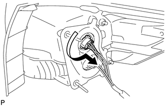
(b) Remove the tail and stop light bulb from the rear combination light socket and wire.
2. REMOVE REAR TURN SIGNAL LIGHT BULB
|
(a) Turn the rear turn signal light bulb and rear combination light socket and wire in the direction indicated by the arrow shown in the illustration, and remove them as a unit. |
|
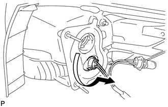
(b) Remove the rear turn signal light bulb from the rear combination light socket and wire.
3. REMOVE REAR BUMPER UPPER RETAINER
|
(a) Remove the 2 screws. |
|
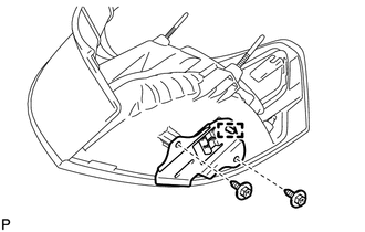
(b) Disengage the guide and remove the rear bumper upper retainer.
 Removal
REMOVAL
PROCEDURE
1. REMOVE REAR DOOR SCUFF PLATE
2. DISCONNECT REAR DOOR OPENING TRIM WEATHERSTRIP
3. REMOVE TONNEAU COVER ASSEMBLY (w/ Tonneau Cover)
4. REMOVE DECK BOARD ASSEMBLY
...
 Reassembly
REASSEMBLY
PROCEDURE
1. INSTALL REAR BUMPER UPPER RETAINER
(a) Engage the guide.
(b) Install the rear bumper upper retainer with the 2 scr ...
Other materials about Toyota Venza:
Data List / Active Test
DATA LIST / ACTIVE TEST
1. DATA LIST
HINT:
Using the Techstream to read the Data List allows the values or states of switches,
sensors, actuators and other items to be read without removing any parts. This non-intrusive
inspection can be very useful bec ...
Removal
REMOVAL
PROCEDURE
1. PRECAUTION
CAUTION:
Be sure to read Precaution thoroughly before servicing (See page
).
NOTICE:
After turning the ignition switch off, waiting time may be required before disconnecting
the cable from the negative (-) battery term ...
Rear Brake Flexible Hose
Components
COMPONENTS
ILLUSTRATION
Removal
REMOVAL
CAUTION / NOTICE / HINT
NOTICE:
If both the left and right side hoses are removed at the same time, be sure to
place identification marks indicating the position on each side.
HINT:
Us ...

0.1806