Toyota Venza: On-vehicle Inspection
ON-VEHICLE INSPECTION
PROCEDURE
1. INSPECT REAR COMBINATION LIGHT ASSEMBLY
|
(a) Disconnect the connector from the rear combination light assembly. |
|
(b) Measure the voltage according to the value(s) in the table below.
Standard Voltage:
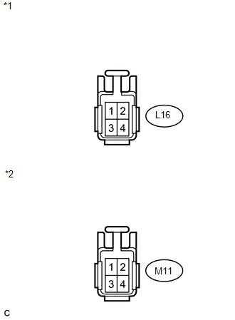
LH Side|
Tester Connection |
Condition |
Specified Condition |
|---|---|---|
|
L16-1 - L16-3 |
Light control switch off |
Below 1 V |
|
Light control switch in tail position |
11 to 14 V |
|
|
L16-2 - L16-3 |
Brake pedal released |
Below 1 V |
|
Brake pedal depressed |
11 to 14 V |
|
|
L16-4 - L16-3 |
Turn signal switch in neutral position |
Below 1 V |
|
Ignition switch ON and turn signal switch in left turn position |
11 to 14 V (60 to 120 times per minute) |
|
Tester Connection |
Condition |
Specified Condition |
|---|---|---|
|
M11-1 - M11-3 |
Light control switch off |
Below 1 V |
|
Light control switch in tail position |
11 to 14 V |
|
|
M11-2 - M11-3 |
Brake pedal released |
Below 1 V |
|
Brake pedal depressed |
11 to 14 V |
|
|
M11-4 - M11-3 |
Turn signal switch neutral position |
Below 1 V |
|
Ignition switch ON and turn signal switch in right turn position |
11 to 14 V (60 to 120 times per minute) |
|
*1 |
Front view of wire harness connector (to Rear Combination Light Assembly LH) |
|
*2 |
Front view of wire harness connector (to Rear Combination Light Assembly RH) |
If the result is not as specified, repair or replace the wire harness or connector.
 Components
COMPONENTS
ILLUSTRATION
ILLUSTRATION
ILLUSTRATION
ILLUSTRATION
ILLUSTRATION
ILLUSTRATION
ILLUSTRATION
...
 Removal
REMOVAL
PROCEDURE
1. REMOVE REAR DOOR SCUFF PLATE
2. DISCONNECT REAR DOOR OPENING TRIM WEATHERSTRIP
3. REMOVE TONNEAU COVER ASSEMBLY (w/ Tonneau Cover)
4. REMOVE DECK BOARD ASSEMBLY
...
Other materials about Toyota Venza:
Vehicle identification
- Vehicle identification number
The vehicle identification number (VIN) is the legal identifier for your vehicle.
This is the primary identification number for your Toyota. It is used in registering
the ownership of your vehicle.
This number is s ...
Wireless Door Lock Buzzer
Components
COMPONENTS
ILLUSTRATION
Installation
INSTALLATION
PROCEDURE
1. INSTALL WIRELESS DOOR LOCK BUZZER
(a) Engage the clamp and install the wireless door lock buzzer.
(b) Connect the ...
Torque Converter Clutch Pressure Control Solenoid Performance (Shift Solenoid
Valve SLU) (P2757)
SYSTEM DESCRIPTION
The TCM uses the signals from the throttle position sensor, air-flow meter, turbine
(input) speed sensor, output speed sensor and crankshaft position sensor to monitor
the engagement condition of the lock-up clutch.
The TCM compares ...

0.1344