Toyota Venza: Removal
REMOVAL
PROCEDURE
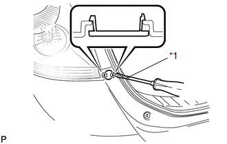
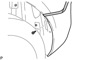
1. REMOVE REAR BUMPER PLATE LH
|
(a) Using a screwdriver with the tip wrapped with protective tape, disengage the 2 claws and remove the rear bumper plate LH. Text in Illustration
|
|
2. REMOVE REAR BUMPER PLATE RH
HINT:
Use the same procedure for the RH side and LH side.
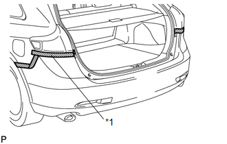
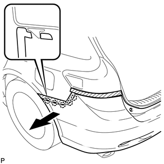
3. REMOVE REAR BUMPER ASSEMBLY
|
(a) Put protective tape around the rear bumper assembly. Text in Illustration
|
|
|
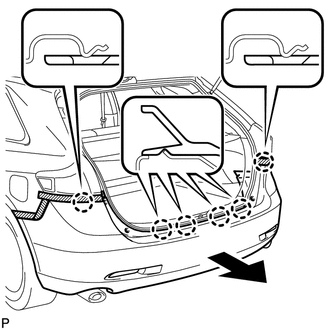
(b) Remove the 2 bolts and 2 screws. |
|
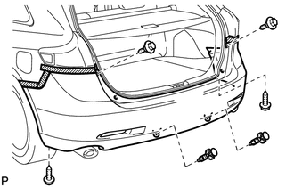
(c) Using a clip remover, remove the 2 clips.
|
(d) Remove the 2 screws and 2 clips. |
|
|
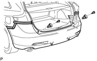
(e) Remove the screw. HINT: Use the same procedure for the RH side and LH side. |
|
|
(f) Disengage the 5 claws. HINT: Use the same procedure for the RH side and LH side. |
|
|
(g) Disengage the 6 claws as shown in the illustration. |
|
(h) w/ Intuitive Parking Assist System:
(1) Disconnect each connector.
(i) Remove the rear bumper assembly.
 Components
COMPONENTS
ILLUSTRATION
ILLUSTRATION
ILLUSTRATION
ILLUSTRATION
...
 Disassembly
DISASSEMBLY
PROCEDURE
1. REMOVE ULTRASONIC SENSOR CLIP (w/ Intuitive Parking Assist System)
2. REMOVE NO. 1 ULTRASONIC SENSOR (w/ Intuitive Parking Assist System)
3. REMOVE NO. 1 ULTRASONIC ...
Other materials about Toyota Venza:
Initialization
INITIALIZATION
1. RESET TRANSAXLE COMPENSATION CODE
NOTICE:
If the following parts have been replaced, initialize the TCM and perform
the following "Reset Memory" and "Perform Road Test to Allow TCM to learn"
steps.
- ...
Customize Parameters
CUSTOMIZE PARAMETERS
1. INTUITIVE PARKING ASSIST SYSTEM (See page
)
2. POWER DOOR LOCK CONTROL SYSTEM (See page
)
3. WIRELESS DOOR LOCK CONTROL SYSTEM (w/ Smart Key System) (See page
)
4. WIRELESS DOOR LOCK CONTROL SYSTEM (w/o Smart Key System) (Se ...
Oil Pressure Switch
Components
COMPONENTS
ILLUSTRATION
Inspection
INSPECTION
PROCEDURE
1. INSPECT ENGINE OIL PRESSURE SWITCH ASSEMBLY
(a) Disconnect the oil pressure switch connector.
(b) Start the engine.
(c) Measure the resistance according to the valu ...

0.1293