Toyota Venza: Removal
REMOVAL
PROCEDURE
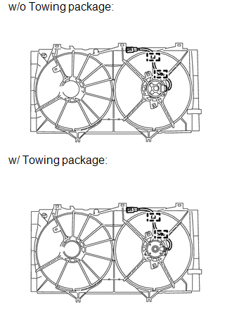
1. REMOVE RADIATOR ASSEMBLY AND FAN ASSEMBLY WITH MOTOR
HINT:
See page .gif)
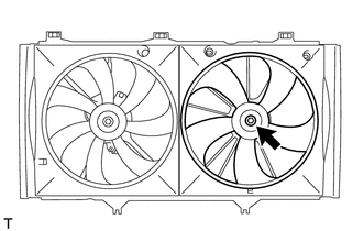
2. REMOVE FAN
|
(a) Remove the nut and fan. |
|
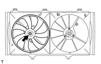
3. REMOVE NO. 2 FAN
|
(a) Remove the nut and No. 2 fan. |
|
4. REMOVE COOLING FAN MOTOR INSULATOR
|
(a) Remove the 2 bolts and cooling fan motor insulator. |
|
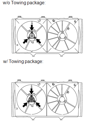
5. REMOVE COOLING FAN MOTOR
|
(a) Remove the 3 screws and cooling fan motor. |
|
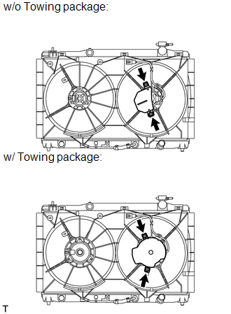
6. REMOVE NO. 2 COOLING FAN MOTOR
|
(a) Disconnect the No. 2 cooling fan motor connector and 2 clamps. |
|
|
(b) Remove the 3 screws and No. 2 cooling fan motor. |
|
 On-vehicle Inspection
ON-VEHICLE INSPECTION
PROCEDURE
1. INSPECT COOLING FAN MOTOR
(a) Check that the motor operates smoothly when the battery is connected
to the cooling fan motor connector.
Text in I ...
 Installation
INSTALLATION
PROCEDURE
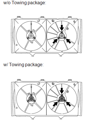
1. INSTALL NO. 2 COOLING FAN MOTOR
(a) Install the No. 2 cooling fan motor with the 3 screws.
Torque:
w/o Towing package :
2.6 N·m {26 kgf·cm, 23 in· ...
Other materials about Toyota Venza:
Data List / Active Test
DATA LIST / ACTIVE TEST
1. ACTIVE TEST
HINT:
Using the Techstream to perform Active Tests allows relays, VSVs, actuators and
other items to be operated without removing any parts. This non-intrusive functional
inspection can be very useful because inter ...
Detection range of the sensors
1. Approximately 1.6 ft. (50 cm)
2. Approximately 4.9 ft. (150 cm)
3. Approximately 2.0 ft. (60 cm)
The diagram shows the detection range of the sensors. Note that the sensors cannot
detect obstacles that are extremely close to the vehicle.
The range o ...
Inspection
INSPECTION
PROCEDURE
1. INSPECT PRELOAD
(a) Using SST and a torque wrench, measure the preload of the backlash
between the driven pinion and ring gear.
SST: 09326-20011
Preload (at Starting):
Item
P ...

0.1567