Toyota Venza: Disassembly
DISASSEMBLY
PROCEDURE
1. REMOVE ULTRASONIC SENSOR CLIP (w/ Intuitive Parking Assist System)
.gif)
2. REMOVE NO. 1 ULTRASONIC SENSOR (w/ Intuitive Parking Assist System)
3. REMOVE NO. 1 ULTRASONIC SENSOR RETAINER (w/ Intuitive Parking Assist System)
4. REMOVE REAR BUMPER WIRE (w/ Intuitive Parking Assist System)
5. REMOVE REFLEX REFLECTOR ASSEMBLY LH
|
(a) Remove the screw. |
|
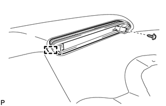
(b) Disengage the guide and remove the reflex reflector assembly LH.
6. REMOVE REFLEX REFLECTOR ASSEMBLY RH
HINT:
Use the same procedure for the RH side and LH side.
7. REMOVE REAR BUMPER SPOILER LH (for 1AR-FE)
|
(a) Remove the outside moulding retainer and clip. Text in Illustration
|
|
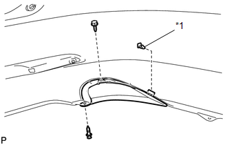
(b) Remove the screw and rear bumper spoiler LH.
8. REMOVE REAR BUMPER SIDE RETAINER LH
|
(a) Remove the screw. |
|
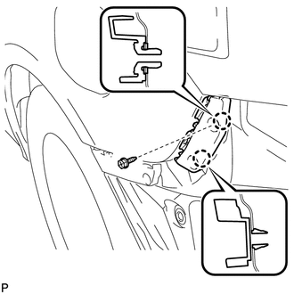
(b) Disengage the 2 claws and remove the rear bumper side retainer LH.
9. REMOVE REAR BUMPER SIDE RETAINER RH
HINT:
Use the same procedure for the RH side and LH side.
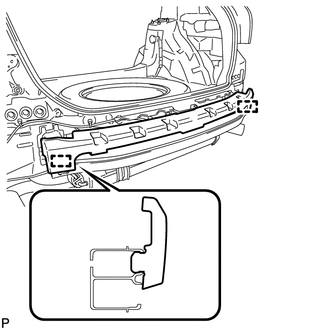
10. REMOVE NO. 2 REAR BUMPER SIDE SUPPORT LH
|
(a) Remove the screw. |
|
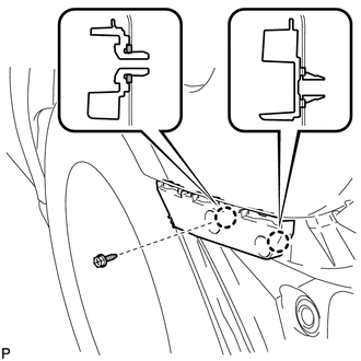
(b) Disengage the 2 claws and remove the No. 2 rear bumper side support LH.
11. REMOVE NO. 2 REAR BUMPER SIDE SUPPORT RH
HINT:
Use the same procedure for the RH side and LH side.
12. REMOVE REAR BUMPER ENERGY ABSORBER
|
(a) Disengage the 2 guides and remove the rear bumper energy absorber. |
|
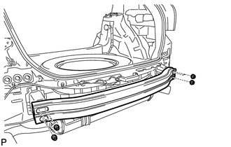
13. REMOVE NO. 1 REAR BUMPER REINFORCEMENT
|
(a) Remove the 6 nuts and No. 1 rear bumper reinforcement. |
|
 Removal
REMOVAL
PROCEDURE
1. REMOVE REAR BUMPER PLATE LH
(a) Using a screwdriver with the tip wrapped with protective tape, disengage
the 2 claws and remove the rear bumper plate LH.
Text ...
 Installation
INSTALLATION
PROCEDURE
1. INSTALL REAR BUMPER ASSEMBLY
(a) w/ Intuitive Parking Assist System:
(1) Connect each connector.
(b) Engage the 6 claws and install the rear bumper assembly a ...
Other materials about Toyota Venza:
Inspection
INSPECTION
PROCEDURE
1. INSPECT GENERATOR PULLEY WITH CLUTCH
(a) Hold the center of the pulley, and confirm that the outer ring turns
counterclockwise and does not turn clockwise.
Text in Illustration
*1
...
Steering Pad Switch Circuit
DESCRIPTION
This circuit sends an operation signal from the steering pad switch assembly
to the radio and display receiver assembly.
If there is an open in the circuit, the audio system cannot be operated using
the steering pad switch assembly.
If there ...
Differential Oil Seal
Components
COMPONENTS
ILLUSTRATION
Replacement
REPLACEMENT
PROCEDURE
1. DRAIN AUTOMATIC TRANSAXLE FLUID
(a) Remove the No. 2 engine under cover and front fender apron LH.
(b) Using a 6 mm socket hexagon wrench, remove the overflow plug ...

0.1247