Toyota Venza: Components
COMPONENTS
ILLUSTRATION
ILLUSTRATION
ILLUSTRATION
ILLUSTRATION
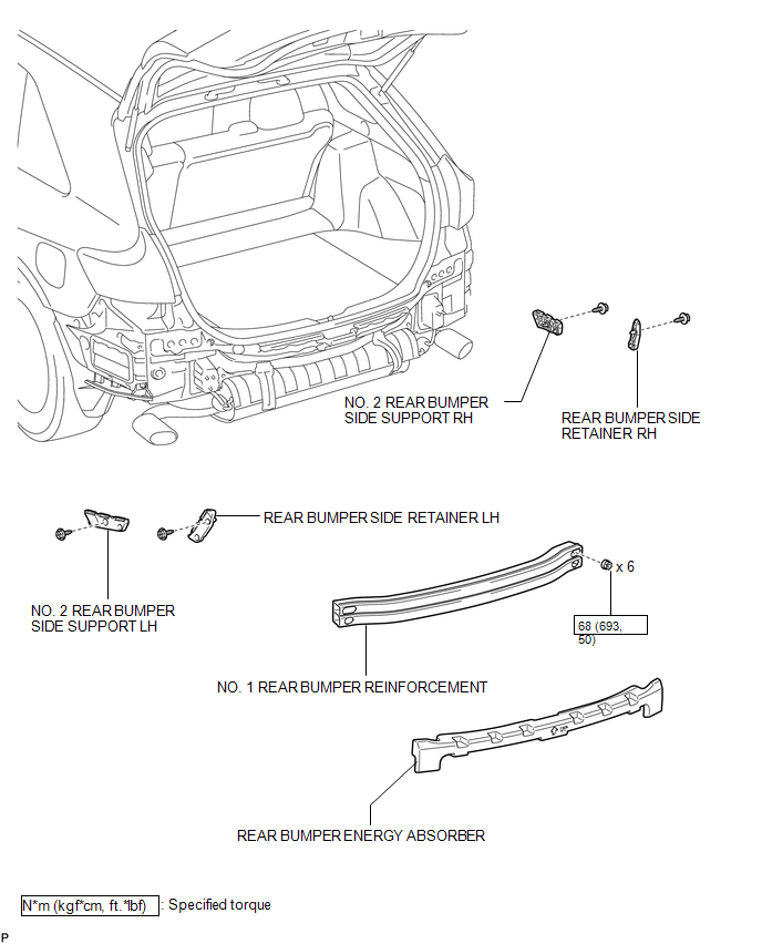
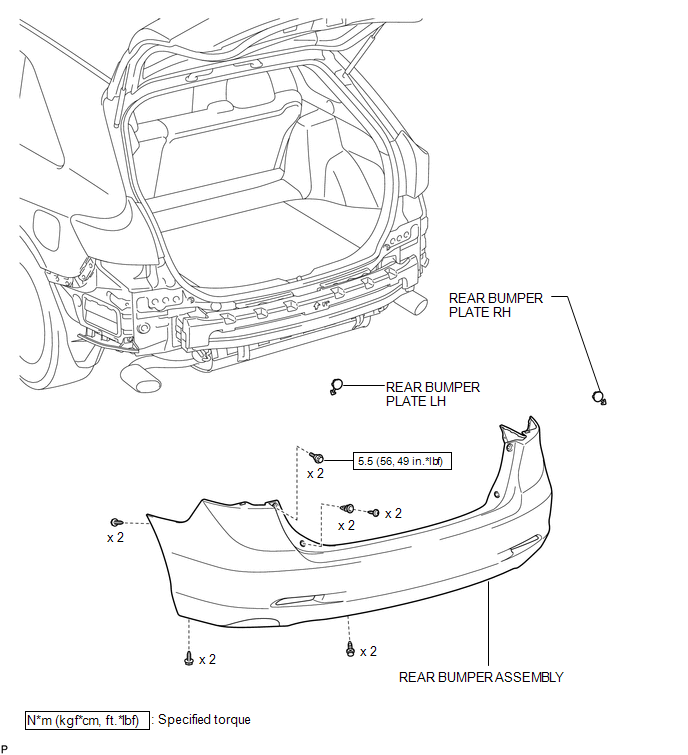
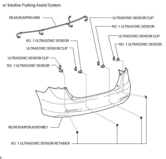
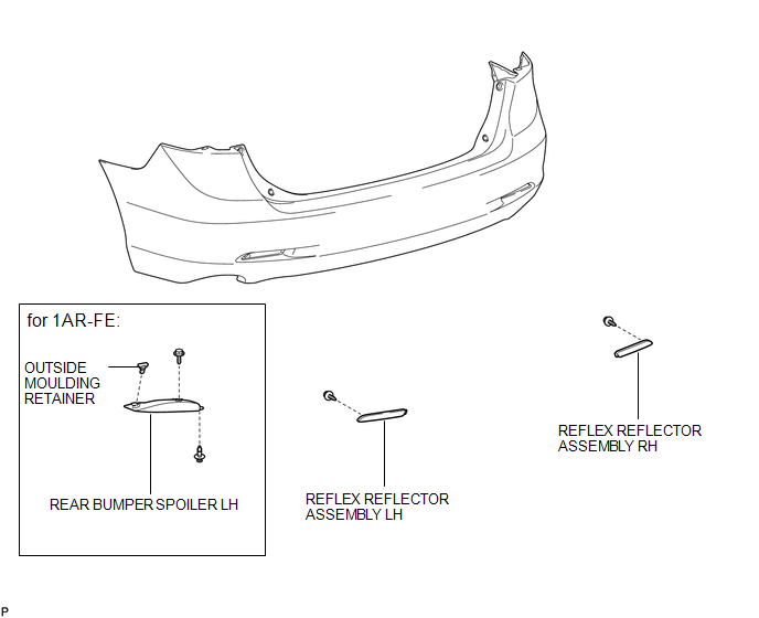
 Rear Bumper
...
 Removal
REMOVAL
PROCEDURE
1. REMOVE REAR BUMPER PLATE LH
(a) Using a screwdriver with the tip wrapped with protective tape, disengage
the 2 claws and remove the rear bumper plate LH.
Text ...
Other materials about Toyota Venza:
Throttle Actuator Control Motor Current Range / Performance (P2118)
DESCRIPTION
The electronic throttle control system has a dedicated power supply circuit.
The voltage (+BM) is monitored and when it is low (below 4 V), the ECM determines
that there is a malfunction in the electronic throttle control system and cuts off
...
GCWR, TWR and Unbraked TWR
Confirm that the gross trailer weight, gross combination weight, gross vehicle
weight, gross axle weight and tongue weight are all within the limits.
- GCWR* and TWR*
► Vehicles without towing package
► Vehicles with towing package
...
Removal
REMOVAL
PROCEDURE
1. DISCONNECT CABLE FROM NEGATIVE BATTERY TERMINAL
NOTICE:
When disconnecting the cable, some systems need to be initialized after the cable
is reconnected (See page ).
2. REMOVE COOL AIR INTAKE DUCT SEAL
3. REMOVE NO. 1 ENGINE CO ...

0.129