Toyota Venza: Removal
REMOVAL
PROCEDURE
1. REMOVE REAR DOOR SCUFF PLATE LH
.gif)
2. DISCONNECT REAR DOOR OPENING TRIM WEATHERSTRIP LH
3. REMOVE TONNEAU COVER ASSEMBLY (w/ Tonneau Cover)
4. REMOVE DECK BOARD ASSEMBLY
5. REMOVE NO. 3 DECK BOARD SUB-ASSEMBLY
6. REMOVE DECK SIDE TRIM BOX LH
7. REMOVE NO. 2 DECK BOARD SUB-ASSEMBLY
8. REMOVE DECK SIDE TRIM BOX RH
9. REMOVE NO. 1 DECK BOARD
10. REMOVE REAR SEAT SUB FLOOR PANEL ASSEMBLY
11. REMOVE REAR FLOOR FINISH PLATE
12. REMOVE REAR SEAT HEADREST ASSEMBLY LH
13. REMOVE REAR SEAT INNER TRACK BRACKET COVER LH
14. REMOVE REAR SEAT OUTER TRACK BRACKET COVER LH
15. DISCONNECT REAR SEAT NO. 2 RECLINING CONTROL CABLE SUB-ASSEMBLY
16. REMOVE REAR SEAT ASSEMBLY LH
17. REMOVE RECLINING REMOTE CONTROL BEZEL LH
18. REMOVE LUGGAGE HOLD BELT STRIKER ASSEMBLY LH
19. DISCONNECT REAR SEAT OUTER BELT ASSEMBLY LH
20. REMOVE DECK TRIM SIDE PANEL ASSEMBLY LH
21. REMOVE ROOF SIDE INNER GARNISH ASSEMBLY LH
22. REMOVE POWER BACK DOOR ROD
|
(a) Using a screwdriver, remove the stop ring along the groove. HINT: Tape the screwdriver tip before use. Text in Illustration
|
|
.png)
(b) Release the ball joint and disengage the power back door rod.
|
(c) Using a screwdriver, remove the stop ring along the groove. HINT: Tape the screwdriver tip before use. Text in Illustration
|
|
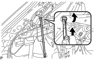
(d) Release the ball joint and remove the power back door rod.
23. REMOVE POWER BACK DOOR UNIT ASSEMBLY
|
(a) Disconnect the connector. |
|
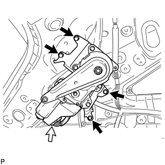
(b) Remove the 4 bolts and power back door unit assembly.
 Components
COMPONENTS
ILLUSTRATION
ILLUSTRATION
ILLUSTRATION
ILLUSTRATION
ILLUSTRATION
...
 Disassembly
DISASSEMBLY
CAUTION / NOTICE / HINT
NOTICE:
When disassembling the multiplex network door ECU, eliminate static electricity
by touching the vehicle body to prevent the components from being damag ...
Other materials about Toyota Venza:
Fuel consumption display (vehicles with Display Audio system)
The actual display may differ from that shown in “Display Audio System Owner’s
Manual”.
• The information related to fuel consumption is also displayed on the multi-information
display. (, 204) • To reset the average fuel consumption data displa ...
Microphone
Components
COMPONENTS
ILLUSTRATION
Removal
REMOVAL
PROCEDURE
1. REMOVE INNER REAR VIEW MIRROR STAY HOLDER COVER
2. REMOVE TELEPHONE MICROPHONE ASSEMBLY (INNER REAR VIEW MIRROR ASSEMBLY)
Installation
INSTALLATION
PROCEDURE
1. INSTALL TE ...
Reassembly
REASSEMBLY
PROCEDURE
1. INSTALL NO. 1 SUNSHADE TRIM SUB-ASSEMBLY
(a) Slide and install the No. 1 sunshade trim sub-assembly.
2. INSTALL NO. 2 SUNSHADE TRIM SUB-ASSEMBLY
(a) Slide and ins ...

0.1161