Toyota Venza: Components
COMPONENTS
ILLUSTRATION
ILLUSTRATION
.png)
ILLUSTRATION
.png)
ILLUSTRATION
ILLUSTRATION

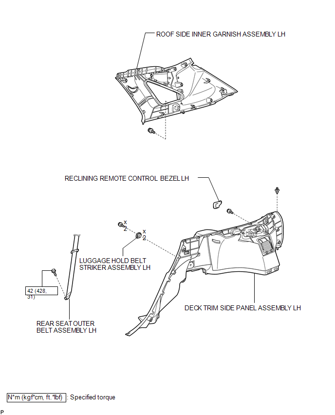
 Removal
REMOVAL
PROCEDURE
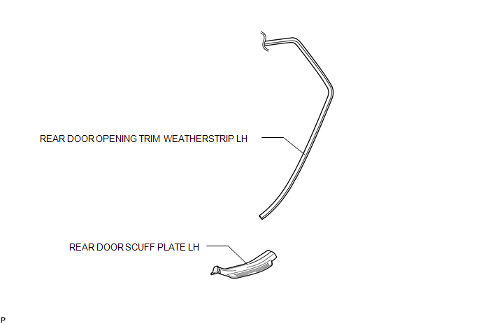
1. REMOVE REAR DOOR SCUFF PLATE LH
2. DISCONNECT REAR DOOR OPENING TRIM WEATHERSTRIP LH
3. REMOVE TONNEAU COVER ASSEMBLY (w/ Tonneau Cover)
4. REMOVE DECK BOARD ASSEMBL ...
Other materials about Toyota Venza:
Installation
INSTALLATION
PROCEDURE
1. INSTALL RADIO AND DISPLAY RECEIVER ASSEMBLY
2. INSTALL NO. 2 RADIO RECEIVER BRACKET
(a) Install the No. 2 radio receiver bracket with the 4 screws.
Torque:
5.0 N·m {51 kgf·cm, 44 in·lbf}
3. INSTALL NO. 1 RADIO RECEIVER BRAC ...
Voice Recognition Microphone Disconnected (B1579)
DESCRIPTION
The radio and display receiver assembly and inner rear view mirror assembly (amplifier
microphone assembly) are connected to each other using the microphone connection
detection signal lines.
This DTC is stored when a microphone connection de ...
USB Audio System Recognition/Play Error
DESCRIPTION
When a USB device or "iPod" is connected to the USB jack of the No. 1 stereo
jack adapter assembly, it must have playable files. The device must also communicate
with and be recognized by the navigation receiver assembly. This diagno ...

0.1809