Toyota Venza: Mass Air Flow Meter
Components
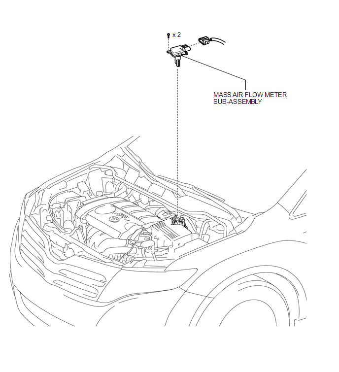
COMPONENTS
ILLUSTRATION
On-vehicle Inspection
ON-VEHICLE INSPECTION
CAUTION / NOTICE / HINT
NOTICE:
- Perform the mass air flow meter inspection according to the procedure below.
- Only replace the mass air flow meter when the mass air flow value in the Data List (with the engine stopped) is not within the normal operating range or there is foreign matter on the mass air flow meter platinum hot wire (heater).
HINT:
Perform "Inspection After Repairs" after replacing the mass air flow meter (See
page .gif) ).
).
PROCEDURE
1. INSPECT MASS AIR FLOW METER SUB-ASSEMBLY
NOTICE:
- Perform the inspection with the vehicle indoors and on a level surface.
- Perform the inspection of the mass air flow meter while it is installed to the air cleaner case (installed to the vehicle).
- During the test, do not use the exhaust air duct to perform suction on the exhaust pipe.
(a) Connect the Techstream to the DLC3.
(b) Turn the ignition switch to ON (do not run the engine).
(c) Turn the Techstream on.
(d) Enter the following menus: Powertrain / Engine / Data List / MAF.
(e) Wait 30 seconds, and read the values on the Techstream.
Standard:
|
Item |
Condition |
Specified Condition |
|---|---|---|
|
MAF |
|
Less than 0.5 g/sec. |
If the result is not as specified, replace the mass air flow meter sub-assembly.
If the result is as specified, inspect the mass air flow meter sub-assembly (See
page ).
Removal
REMOVAL
PROCEDURE
1. REMOVE MASS AIR FLOW METER SUB-ASSEMBLY
|
(a) Disconnect the mass air flow meter connector. |
|
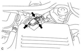
(b) Remove the 2 screws and mass air flow meter.
Inspection
INSPECTION
PROCEDURE
1. INSPECT MASS AIR FLOW METER SUB-ASSEMBLY
|
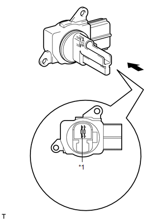
(a) Perform a visual check for any foreign matter on the platinum hot wire (heater) of the mass air flow meter shown in the illustration. Text in Illustration
OK: There is no foreign material. |
|
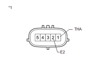
(b) Check the intake air temperature sensor (built into the mass air flow meter).
|
(1) Measure the resistance according to the value(s) in the table below. Standard Resistance:
If the result is not as specified, replace the mass air flow meter sub-assembly. Text in Illustration
|
|
Installation
INSTALLATION
PROCEDURE
1. INSTALL MASS AIR FLOW METER SUB-ASSEMBLY
|
(a) Install the mass air flow meter with the 2 screws. NOTICE: Make sure that the O-ring is not cracked or jammed when installing the mass air flow meter. HINT: Perform "Inspection After Repair" after replacing the mass air flow meter
sub-assembly (See page |
|
.gif) ).
)..png)
(b) Connect the mass air flow meter connector.
 Knock Sensor
Components
COMPONENTS
ILLUSTRATION
Removal
REMOVAL
PROCEDURE
1. REMOVE INTAKE MANIFOLD
(a) Remove the intake manifold (See page ).
2. REMOVE KNOCK SENSOR
(a) Disconnect the ...
 Relay
Relay
On-vehicle Inspection
ON-VEHICLE INSPECTION
PROCEDURE
1. INSPECT IG2 RELAY
(a) Remove the IG2 relay from the relay block.
(b) Measure the resistance according to the value(s) in the ...
Other materials about Toyota Venza:
System Description
SYSTEM DESCRIPTION
1. ILLUMINATED ENTRY SYSTEM
(a) The illuminated entry system has the following control functions:
Control
Outline
Lights that Operate
Actuation Area-linked*2
When a registered k ...
On-vehicle Inspection
ON-VEHICLE INSPECTION
PROCEDURE
1. INSPECT FOR COOLANT LEAK
HINT:
The sliding surface inside the engine water pump assembly is lubricated
by engine coolant. As some engine coolant is discharged during normal operation,
engine coolant residu ...
Calibration
CALIBRATION
1. DESCRIPTION
(a) Follow the chart below to perform calibration.
Parts to be Replaced
Necessary Operation
Brake actuator assembly (Skid control ECU)
Perform engine variant learning
2. ...

0.165