
Toyota Venza: Components
COMPONENTS
ILLUSTRATION
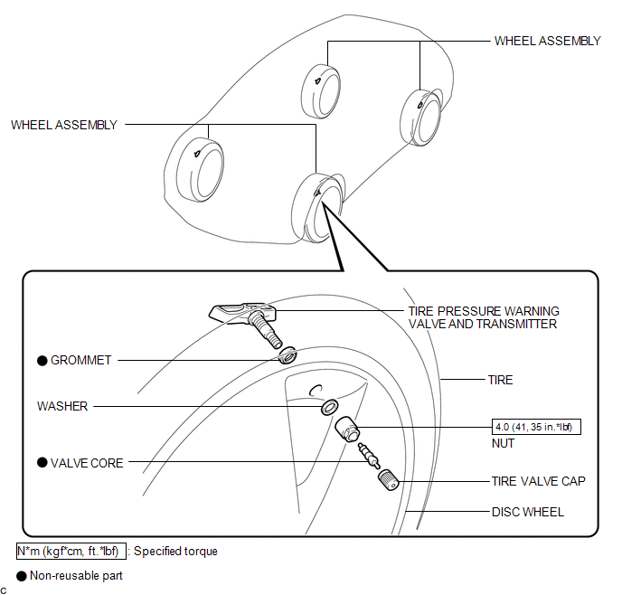

 Removal
REMOVAL
PROCEDURE
1. REMOVE WHEEL ASSEMBLY
2. REMOVE TIRE PRESSURE WARNING VALVE AND TRANSMITTER
(a) Remove the tire valve cap.
NOTICE:
Keep the removed tire valve cap.
(b) Remove the valve cor ...
Other materials about Toyota Venza:
Reassembly
REASSEMBLY
PROCEDURE
1. INSTALL AIR OUTLET CONTROL SERVO MOTOR SUB-ASSEMBLY
(a) Check that the slots, links and gears of the air outlet control servo
motor sub-assembly are positioned in the correct orientation as shown in
the illustratio ...
Intake Air Temperature Sensor Gradient Too High (P0111)
DESCRIPTION
The intake air temperature sensor, mounted on the mass air flow meter,
monitors the intake air temperature. The intake air temperature sensor has
a built-in thermistor with a resistance that varies according to the temperature
...
How To Proceed With Troubleshooting
CAUTION / NOTICE / HINT
HINT:
Use the following procedures to troubleshoot the power back door system.
*: Use the Techstream.
PROCEDURE
1.
VEHICLE BROUGHT TO WORKSHOP
NEXT
...

0.1213