Toyota Venza: Removal
REMOVAL
PROCEDURE
1. REMOVE REAR WHEELS
2. SEPARATE REAR STABILIZER LINK ASSEMBLY LH
|
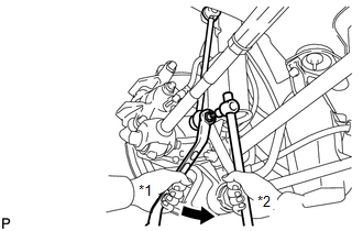
(a) Remove the nut and separate the rear stabilizer link assembly LH from the rear stabilizer bar. Text in Illustration
HINT: If the ball joint turns together with the nut, use a hexagon wrench (5 mm) to hold the stud bolt. |
|
3. SEPARATE REAR STABILIZER LINK ASSEMBLY RH
HINT:
Perform the same procedure as the LH side.
4. REMOVE REAR STABILIZER BAR
.gif)
5. SEPARATE REAR HEIGHT CONTROL SENSOR SUB-ASSEMBLY (w/ HID Headlight System)
|
(a) Remove the nut and separate the rear height control sensor sub-assembly from the rear No. 2 suspension arm assembly RH. NOTICE: Use wire or an equivalent tool to keep the rear height control sensor link from hanging down. |
|
.png)
6. REMOVE REAR NO. 2 SUSPENSION ARM ASSEMBLY LH
|
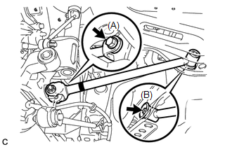
(a) Remove the bolt (A) and the nut, and separate the rear No. 2 suspension arm assembly LH from the rear axle carrier sub-assembly LH. NOTICE: Since a stopper nut is used, loosen the bolt. |
|
.png)
(b) Remove the bolt (B) and the rear No. 2 suspension arm assembly LH.
7. REMOVE REAR NO. 2 SUSPENSION ARM ASSEMBLY RH
HINT:
Perform the same procedure as the LH side.
8. REMOVE REAR NO. 1 SUSPENSION ARM ASSEMBLY LH
|
(a) Remove the bolt and the nut, and separate the rear No. 1 suspension arm assembly LH from the rear axle carrier sub-assembly. NOTICE: Since a stopper nut is used, loosen the bolt. |
|
(b) Remove the bolt and the rear No. 1 suspension arm assembly LH.
9. REMOVE REAR NO. 1 SUSPENSION ARM ASSEMBLY RH
HINT:
Perform the same procedure as the LH side.
 Installation
INSTALLATION
PROCEDURE
1. TEMPORARILY INSTALL REAR NO. 1 SUSPENSION ARM ASSEMBLY LH
(a) Temporarily install the rear No. 1 suspension arm assembly LH to
the rear suspension member wi ...

Other materials about Toyota Venza:
Problem Symptoms Table
PROBLEM SYMPTOMS TABLE
NOTICE:
After replacing the stereo component tuner assembly of vehicles subscribed to
pay-type satellite radio broadcasts, XM radio ID registration is necessary (w/ SDARS
System).
HINT:
Use the table below to help determi ...
Occupant Classification Sensor Power Supply Circuit Malfunction (B1793)
DESCRIPTION
The occupant classification sensor power supply circuit consists of the occupant
classification ECU and occupant classification sensors.
DTC B1793 is recorded when a malfunction is detected in the occupant classification
sensor power supply c ...
Data List / Active Test
DATA LIST / ACTIVE TEST
1. DATA LIST
HINT:
Using the Techstream to read the Data List allows the values or states of switches,
sensors, actuators and other items to be read without removing any parts. This non-intrusive
inspection can be very useful bec ...

2.3046