Toyota Venza: Steering Knuckle
Components
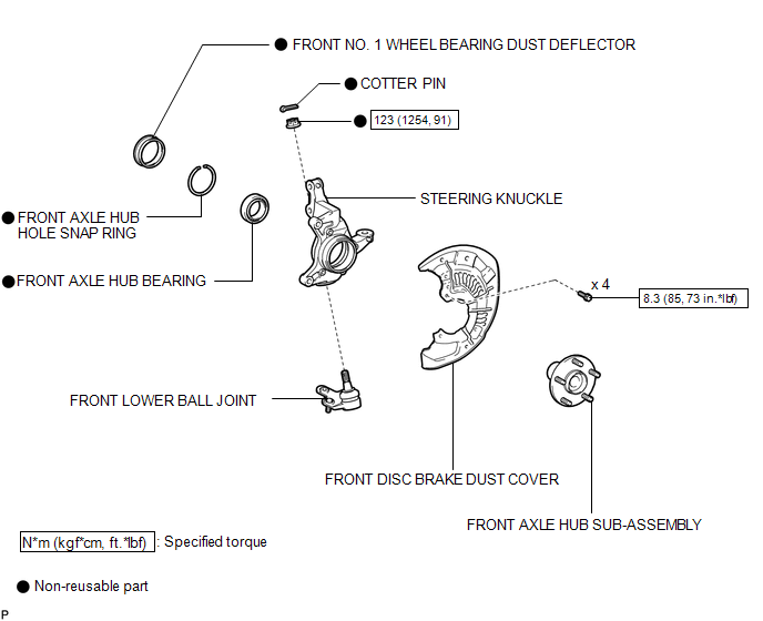
COMPONENTS
ILLUSTRATION
Removal
REMOVAL
CAUTION / NOTICE / HINT
HINT:
- Use the same procedure for the RH side and LH side.
- The procedure listed below is for the LH side.
PROCEDURE
1. REMOVE FRONT AXLE ASSEMBLY
HINT:
Refer to procedures up to "Remove Front Axle Assembly" (See page
.gif) ).
).
2. REMOVE FRONT LOWER BALL JOINT
3. REMOVE FRONT NO. 1 WHEEL BEARING DUST DEFLECTOR
4. REMOVE FRONT AXLE HUB HOLE SNAP RING
5. REMOVE FRONT AXLE HUB SUB-ASSEMBLY
6. REMOVE FRONT DISC BRAKE DUST COVER
7. REMOVE STEERING KNUCKLE
(a) Place the bearing inner race (outside) on the front axle hub bearing.
|
(b) Using SST, V-blocks and a press, remove the front axle hub bearing from the steering knuckle. If the steering knuckle cannot be kept level using SST, stabilize the steering knuckle using a washer or an equivalent tool. Text in Illustration
SST: 09527-21011 SST: 09950-60010 09951-00440 09952-06010 SST: 09950-60020 09951-00750 SST: 09950-70010 09951-07100 NOTICE: Keep the steering knuckle level. |
|
.png)
Installation
INSTALLATION
CAUTION / NOTICE / HINT
HINT:
- Use the same procedure for the RH side and LH side.
- The procedure listed below is for the LH side.
PROCEDURE
1. INSTALL STEERING KNUCKLE
|
(a) Using SST and a press, install a new front axle hub bearing to the steering knuckle. SST: 09950-60020 09951-00810 SST: 09950-70010 09951-07100 |
|
.png)
2. INSTALL FRONT DISC BRAKE DUST COVER
.gif)
3. INSTALL FRONT AXLE HUB SUB-ASSEMBLY
4. INSTALL FRONT AXLE HUB HOLE SNAP RING
5. INSTALL FRONT NO. 1 WHEEL BEARING DUST DEFLECTOR
6. INSTALL FRONT LOWER BALL JOINT
7. INSTALL FRONT AXLE ASSEMBLY
HINT:
Refer to the procedures from "Install Front Axle Assembly" (See page
).
 Replacement
REPLACEMENT
CAUTION / NOTICE / HINT
HINT:
Use the same procedure for the RH side and LH side.
The procedure listed below is for the LH side.
PROCEDURE
1. DRAIN DIFFERENTIAL OIL
...

Other materials about Toyota Venza:
Installation
INSTALLATION
PROCEDURE
1. INSTALL REAR DRIVE SHAFT ASSEMBLY
(a) Align the shaft splines and install the rear drive shaft assembly
using a screwdriver and hammer.
NOTICE:
Set the snap ring with the opening facing downward.
...
Reassembly
REASSEMBLY
PROCEDURE
1. INSTALL NO. 2 STEERING RACK BOOT
(a) Apply lithium soap base glycol grease to the inside of the small
opening of a new No. 2 steering rack boot.
(b) Install the No. 2 ste ...
Installation
INSTALLATION
PROCEDURE
1. INSPECT TORQUE CONVERTER ASSEMBLY
2. INSTALL TORQUE CONVERTER ASSEMBLY
(a) Engage the splines of the input shaft and turbine runner.
(b) Engage the splines o ...

0.1582