Toyota Venza: Installation
INSTALLATION
PROCEDURE
1. TEMPORARILY INSTALL REAR NO. 1 SUSPENSION ARM ASSEMBLY LH
|
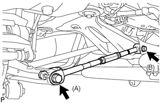
(a) Temporarily install the rear No. 1 suspension arm assembly LH to the rear suspension member with the bolt (B). Text in Illustration
NOTICE: Ensure that the identification mark faces the rear side of the vehicle. |
|
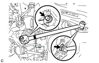
(b) Temporarily install the rear No. 1 suspension arm assembly LH to the rear axle carrier sub-assembly with the bolt (A) and the nut.
NOTICE:
Since a stopper nut is used, temporarily tighten the bolt.
2. TEMPORARILY INSTALL REAR NO. 1 SUSPENSION ARM ASSEMBLY RH
HINT:
Perform the same procedure as the LH side.
3. TEMPORARILY INSTALL REAR NO. 2 SUSPENSION ARM ASSEMBLY LH
|
(a) Temporarily install the rear No. 2 suspension arm assembly LH to the rear suspension member with the bolt (B). Text in Illustration
NOTICE: Ensure that the identification mark faces the rear side of the vehicle. |
|
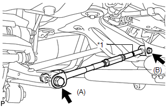
(b) Temporarily install the rear No. 2 suspension arm assembly LH to the rear axle carrier sub-assembly LH with the bolt (A) and the nut.
NOTICE:
Since a stopper nut is used, temporarily tighten the bolt.
4. TEMPORARILY INSTALL REAR NO. 2 SUSPENSION ARM ASSEMBLY RH
|
(a) Temporarily install the rear No. 2 suspension arm assembly RH to the rear suspension member with the bolt (B). Text in Illustration
NOTICE: Ensure that the identification mark faces the rear side of the vehicle. |
|
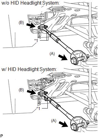
(b) Temporarily install the rear No. 2 suspension arm assembly RH to the rear axle carrier sub-assembly RH with the bolt (B) and the nut.
NOTICE:
Since a stopper nut is used, temporarily tighten the bolt.
5. CONNECT REAR HEIGHT CONTROL SENSOR SUB-ASSEMBLY (w/ HID Headlight System)
|
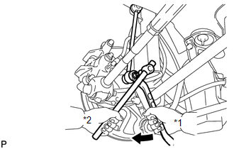
(a) Connect the rear height control sensor sub-assembly to the rear No. 2 suspension arm assembly RH with the nut. Torque: 5.4 N·m {55 kgf·cm, 48 in·lbf} |
|
6. STABILIZE SUSPENSION
(a) Install the rear wheels.
Torque:
103 N·m {1050 kgf·cm, 76 ft·lbf}
(b) Lower the vehicle to the ground.
(c) Bounce the vehicle up and down at the corners to stabilize the rear suspension.
(d) Remove the rear wheels.
7. FULLY TIGHTEN REAR NO. 1 SUSPENSION ARM ASSEMBLY LH
|
(a) Support the rear axle carrier sub-assembly using a jack and wooden block as shown in the illustration. Text in Illustration
NOTICE: Do not bend the brake dust cover. |
|
.png)
|
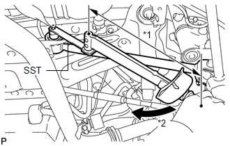
(b) Jack up the rear axle carrier sub-assembly LH to set the rear No. 1 suspension arm assembly LH in the tightening position as shown in the illustration. Standard angle (A): 4°36' (4.6°) Standard length (B): 38.6 mm (1.52 in.) CAUTION: Do not jack up the rear axle carrier sub-assembly LH too high as the vehicle may fall. HINT: If the rear No. 1 suspension arm assembly LH cannot be positioned as shown in the illustration even when the rear axle carrier sub-assembly LH is jacked up, apply additional load to the vehicle such as by having a person sit in the rear seat. |
|
.png)
|
(c) Using SST and a socket wrench (19 mm), fully tighten the bolt in the tightening position. Text in Illustration
SST: 09961-00950 Torque: Specified Tightening Torque : 120 N·m {1224 kgf·cm, 89 ft·lbf} NOTICE:
HINT:
|
|
|
(d) Fully tighten the bolt in the tightening position. Torque: 112 N·m {1142 kgf·cm, 83 ft·lbf} NOTICE: Since a stopper nut is used, fully tighten the bolt. |
|
8. FULLY TIGHTEN REAR NO. 1 SUSPENSION ARM ASSEMBLY RH
HINT:
Perform the same procedure as the LH side.
9. FULLY TIGHTEN REAR NO. 2 SUSPENSION ARM ASSEMBLY LH
|
(a) Support the rear axle carrier sub-assembly using a jack and wooden block as shown in the illustration. Text in Illustration
NOTICE: Do not bend the brake dust cover. |
|
|
(b) Jack up the rear axle carrier sub-assembly LH to set the rear No. 2 suspension arm assembly LH in the tightening position as shown in the illustration. Standard angle (A): 4°36' (4.6°) Standard length (B): 39.1 mm (1.54 in.) CAUTION: Do not jack up the rear axle carrier sub-assembly LH too high as the vehicle may fall. HINT: If the rear No. 2 suspension arm assembly LH cannot be positioned as shown in the illustration even when the rear axle carrier sub-assembly LH is jacked up, apply additional load to the vehicle such as by having a person sit in the rear seat. |
|
.png)
|
(c) Fully tighten the bolts in the tightening position. Torque: Bolt (A) : 112 N·m {1142 kgf·cm, 83 ft·lbf} Bolt (B) : 120 N·m {1224 kgf·cm, 89 ft·lbf} NOTICE: Since a stopper nut is used, fully tighten the bolt (A) and (B). |
|
10. FULLY TIGHTEN REAR NO. 2 SUSPENSION ARM ASSEMBLY RH
HINT:
Perform the same procedure as the LH side.
11. INSTALL REAR STABILIZER BAR
.gif)
12. INSTALL REAR STABILIZER LINK ASSEMBLY LH
|
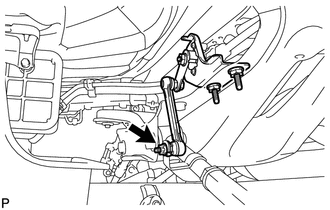
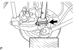
(a) Install the rear stabilizer link assembly LH to the rear stabilizer bar with the nut. Text in Illustration
Torque: 39 N·m {400 kgf·cm, 29 ft·lbf} HINT: If the ball joint turns together with the nut, use a hexagon wrench (5 mm) to hold the stud bolt. |
|
13. INSTALL REAR STABILIZER LINK ASSEMBLY RH
HINT:
Perform the same procedure as the LH side.
14. INSTALL REAR WHEEL
Torque:
103 N·m {1050 kgf·cm, 76 ft·lbf}
15. INSPECT AND ADJUST REAR WHEEL ALIGNMENT
(a) Inspect and adjust the rear wheel alignment (See page
).
16. HEIGHT CONTROL SENSOR SIGNAL INITIALIZATION (w/ HID Headlight System)
(a) Initialize the height control sensor signal (See page
).
17. INSPECT AND ADJUST HEADLIGHT AIMING (w/ HID Headlight System)
(a) Inspect and adjust the headlight aiming (See page
).
 Components
COMPONENTS
ILLUSTRATION
ILLUSTRATION
...
 Removal
REMOVAL
PROCEDURE
1. REMOVE REAR WHEELS
2. SEPARATE REAR STABILIZER LINK ASSEMBLY LH
(a) Remove the nut and separate the rear stabilizer link assembly LH
from the rear stabilizer ba ...
Other materials about Toyota Venza:
Television Camera
Components
COMPONENTS
ILLUSTRATION
ILLUSTRATION
Removal
REMOVAL
PROCEDURE
1. REMOVE BACK DOOR PANEL TRIM ASSEMBLY
2. REMOVE REAR WIPER ARM HEAD CAP
3. REMOVE REAR WIPER ARM AND BLADE ASSEMBLY
4. REMOVE REAR WIPER MOTOR GROMMET
5. ...
Installation
INSTALLATION
PROCEDURE
1. INSTALL ENGINE COOLANT TEMPERATURE SENSOR
(a) Install a new gasket to the sensor.
Text in Illustration
*1
New Gasket
...
Inspection
INSPECTION
PROCEDURE
1. INSPECT OUTER MIRROR SWITCH ASSEMBLY (w/o Memory)
(a) The L position of the left/right adjustment switch: Measure the resistance
according to the value(s) in the table below.
Standard Resistance (for Left Side):
Tes ...

0.1176