Toyota Venza: Removal
REMOVAL
PROCEDURE
1. ALIGN FRONT WHEELS FACING STRAIGHT AHEAD
2. DISCONNECT CABLE FROM NEGATIVE BATTERY TERMINAL
NOTICE:
When disconnecting the cable, some systems need to be initialized after the cable
is reconnected (See page .gif) ).
).
3. REMOVE FRONT WHEELS
4. REMOVE NO. 1 ENGINE UNDER COVER
5. REMOVE NO. 2 ENGINE UNDER COVER
6. SEPARATE FRONT FENDER LINER LH
7. SEPARATE FRONT FENDER LINER RH
8. REMOVE FRONT FENDER APRON SEAL LH
9. REMOVE FRONT FENDER APRON SEAL RH
10. REMOVE FRONT FLOOR BRACE
11. DRAIN ENGINE COOLANT
12. REMOVE WINDSHIELD WIPER MOTOR AND LINK ASSEMBLY
(See page )
13. REMOVE OUTER COWL TOP PANEL
14. REMOVE COOL AIR INTAKE DUCT SEAL
15. REMOVE V-BANK COVER SUB-ASSEMBLY
16. REMOVE INLET NO. 2 AIR CLEANER
17. REMOVE AIR CLEANER CAP WITH HOSE
18. REMOVE AIR CLEANER CASE
19. REMOVE BATTERY
20. REMOVE INLET NO. 1 AIR CLEANER
21. REMOVE INTAKE AIR SURGE TANK ASSEMBLY
(See page )
22. DISCONNECT ENGINE WIRE
23. REMOVE ECM
(See page )
24. REMOVE FRONT DOOR SCUFF PLATE LH
25. REMOVE COWL SIDE TRIM SUB-ASSEMBLY LH
26. REMOVE TAIL EXHAUST PIPE ASSEMBLY (for AWD)
27. REMOVE CENTER EXHAUST PIPE ASSEMBLY (for AWD)
28. REMOVE FRONT NO. 3 EXHAUST PIPE SUB-ASSEMBLY
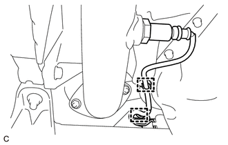
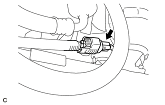
29. DISCONNECT HEATED OXYGEN SENSOR (for Bank 2)
|
(a) Disengage the 2 wire harness clamps. |
|
|
(b) Disconnect the heated oxygen sensor connector. |
|
30. REMOVE FRONT EXHAUST PIPE ASSEMBLY
31. REMOVE PROPELLER WITH CENTER BEARING SHAFT ASSEMBLY (for AWD)
32. SECURE STEERING WHEEL
33. REMOVE FRONT AXLE SHAFT NUT LH
34. REMOVE FRONT AXLE SHAFT NUT RH
HINT:
Perform the same procedure as for the LH side.
35. SEPARATE TIE ROD ASSEMBLY LH
36. SEPARATE TIE ROD ASSEMBLY RH
HINT:
Perform the same procedure as for the LH side.
37. SEPARATE FRONT STABILIZER LINK ASSEMBLY LH
38. SEPARATE FRONT STABILIZER LINK ASSEMBLY RH
HINT:
Perform the same procedure as for the LH side.
39. REMOVE FRONT LOWER SUSPENSION ARM LH
40. REMOVE FRONT LOWER SUSPENSION ARM RH
HINT:
Perform the same procedure as for the LH side.
41. SEPARATE FRONT DRIVE SHAFT ASSEMBLY LH
42. SEPARATE FRONT DRIVE SHAFT ASSEMBLY RH
HINT:
Perform the same procedure as for the LH side.
43. SEPARATE STEERING INTERMEDIATE SHAFT ASSEMBLY
44. SEPARATE FRONT NO. 1 STABILIZER BRACKET LH (for AWD)
45. SEPARATE FRONT NO. 1 STABILIZER BRACKET RH (for AWD)
HINT:
Perform the same procedure as for the LH side.
46. SEPARATE FRONT STABILIZER BAR WITH FRONT STABILIZER LINK ASSEMBLY (for AWD)
47. SEPARATE STEERING LINK ASSEMBLY (for AWD)
48. SEPARATE FRONT ENGINE MOUNTING INSULATOR ASSEMBLY
|
(a) Remove the 3 nuts and separate the front engine mounting insulator assembly from the front frame assembly. |
|
.png)
49. SEPARATE ENGINE MOUNTING INSULATOR LH
(a) Remove the 2 hole plugs.
|
(b) Remove the 3 nuts and separate the engine mounting insulator LH from the front frame assembly. |
|
.png)
50. SEPARATE ENGINE MOUNTING INSULATOR RH
(a) Remove the 2 hole plugs.
|
(b) Remove the 3 nuts and separate the engine mounting insulator RH from the front frame assembly. |
|
.png)
51. SEPARATE REAR ENGINE MOUNTING INSULATOR ASSEMBLY
(a) Remove the 2 hole plugs.
|
(b) Remove the 2 nuts and separate the rear engine mounting insulator assembly from the front frame assembly. |
|
.png)
52. DISCONNECT NO. 1 RADIATOR HOSE
53. INSTALL ENGINE HANGERS
54. INSTALL ENGINE SUPPORT BRIDGE
55. INSTALL BELT
56. REMOVE FRONT FRAME ASSEMBLY
|
(a) Disengage the 2 wire harness clamps. |
|
.png)
|
(b) Wind the chain with the chain block assembly to lift the engine with automatic transaxle assembly. Text in Illustration
NOTICE:
|
|

(c) Support the front frame assembly with an engine lifter using 4 attachments or equivalent tools as shown in the illustration.
.png) Text in Illustration
Text in Illustration
|
*a |
Engine Lifter |
|
*b |
Attachment |
.png) |
Attachment Placement Location |
CAUTION:
- The front frame assembly is a heavy component. Make sure that it is supported securely.
- Make sure to secure the front frame assembly to prevent it from dropping.
NOTICE:
Use the attachments to keep the front frame assembly level.
|
(d) Remove the 4 bolts, 2 nuts, and frame side rail plates RH and LH. |
|
.png)
(e) Remove the 4 bolts, 2 nuts, and front suspension member rear braces RH and LH.
(f) Slowly lower the front frame assembly.
NOTICE:
When lowering the front frame assembly, be careful not to damage the vehicle body or other components installed to the vehicle.
57. SEPARATE FRONT NO. 1 STABILIZER BRACKET LH (for 2WD)
|
(a) Remove the 2 bolts and separate the front No. 1 stabilizer bracket LH from the front frame assembly. |
|
.png)
58. SEPARATE FRONT NO. 1 STABILIZER BRACKET RH (for 2WD)
HINT:
Perform the same procedure as for the LH side.
59. REMOVE FRONT STABILIZER BAR WITH FRONT STABILIZER LINK ASSEMBLY (for 2WD)
60. REMOVE STEERING LINK ASSEMBLY (for 2WD)
61. REMOVE FRONT LOWER SUSPENSION ARM LH
62. REMOVE FRONT LOWER SUSPENSION ARM RH
HINT:
Perform the same procedure as for the LH side.
63. REMOVE FRONT SUSPENSION MEMBER DYNAMIC DAMPER (for 2WD)
|
(a) Remove the 2 bolts and front suspension member dynamic damper. |
|
.png)
64. REMOVE FRONT SUSPENSION MEMBER BODY MOUNTING FRONT STOPPER
65. REMOVE FRONT SUSPENSION MEMBER BODY MOUNTING REAR STOPPER
66. REMOVE FRONT SUSPENSION MEMBER BODY MOUNTING FRONT CUSHION
|
(a) Install SST as shown in the illustration. Text in Illustration
SST: 09830-10010 09830-01010 09830-01040 09830-01050 SST: 09950-40011 09951-04020 09952-04010 09955-04011 |
|
.png)
|
(b) Using SST, remove the front suspension member body mounting front cushion. Text in Illustration
NOTICE:
|
|
.png)
67. REMOVE FRONT SUSPENSION MEMBER BODY MOUNTING REAR CUSHION LH
|
(a) Install SST as shown in the illustration. SST: 09830-10010 09830-01010 09830-01040 09830-01050 SST: 09950-40011 09951-04020 09952-04010 09954-04010 09955-04011 Text in Illustration
|
|
|
(b) Using SST, remove the front suspension member body mounting rear cushion LH. Text in Illustration
SST: 09830-10010 09830-01010 09830-01040 09830-01050 SST: 09950-40011 09951-04020 09952-04010 09954-04010 09955-04011 NOTICE:
|
|
.png)
68. REMOVE FRONT SUSPENSION MEMBER BODY MOUNTING REAR CUSHION RH
HINT:
Perform the same procedure as for the LH side.
 Components
COMPONENTS
ILLUSTRATION
ILLUSTRATION
ILLUSTRATION
ILLUSTRATION
ILLUSTRATION
ILLUSTRATION
ILLUSTRATION
ILLUSTRATION
ILLUSTRATION
ILLUSTRATION
ILLUSTRATION
ILLUSTRATION ...
 Installation
INSTALLATION
PROCEDURE
1. INSTALL FRONT SUSPENSION MEMBER BODY MOUNTING REAR CUSHION LH
(a) Temporarily install a new front suspension member body mounting rear
cushion LH while conf ...
Other materials about Toyota Venza:
Installation
INSTALLATION
PROCEDURE
1. INSTALL ROOF DRIP SIDE FINISH MOULDING CLIP (w/o Sliding Roof)
NOTICE:
If reusing the clips, do not remove the double-sided tape remaining
on the clips and where the clips will be installed on the body.
If installi ...
Initialization
INITIALIZATION
1. INITIALIZE POWER WINDOW CONTROL SYSTEM (POWER WINDOW REGULATOR MOTOR ASSEMBLY
(ALL DOORS))
CAUTION:
When the power window regulator motor assembly is reinstalled or replaced, the
power window control system must be initialized. Functio ...
Front Seat Inner Belt Assembly
Components
COMPONENTS
ILLUSTRATION
ILLUSTRATION
Inspection
INSPECTION
PROCEDURE
1. INSPECT FRONT SEAT INNER BELT ASSEMBLY LH (w/ Seat Position Memory System)
(a) Measure the resistance according to the value(s) in the table below.
...

0.15