Toyota Venza: Theft Deterrent System Communication Line High Fixation (B279A)
DESCRIPTION
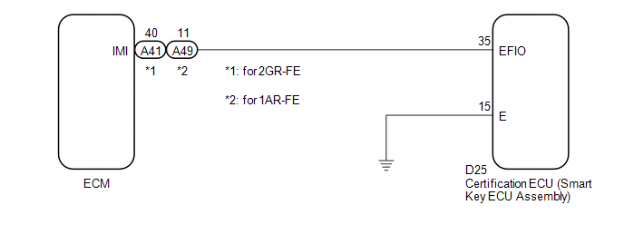
If the communication line (EFIO - IMI) to the certification ECU (smart key ECU assembly) is stuck high output (e.g. shorted to +B), the ECM stores this DTC.
|
DTC No. |
DTC Detection Condition |
Trouble Area |
|---|---|---|
|
B279A |
When the communication line (EFIO - IMI) between ECM and certification ECU (smart key ECU assembly) is stuck high output. |
|
WIRING DIAGRAM
CAUTION / NOTICE / HINT
NOTICE:
If the certification ECU (smart key ECU assembly) is replaced, register the key
(See page .gif) ).
).
PROCEDURE
|
1. |
CHECK DTC OUTPUT |
(a) Clear the DTCs (See page ).
(b) Recheck for DTCs (See page ).
HINT:
If any DTCs other than DTC B279A are output, troubleshoot those DTCs first.
|
Result |
Proceed to |
|---|---|
|
DTC B279A is output |
A |
|
DTC B279A and other DTCs are output |
B |
| B | .gif) |
GO TO DIAGNOSTIC TROUBLE CODE CHART |
|
.gif)
|
2. |
CHECK HARNESS AND CONNECTOR (CERTIFICATION ECU - ECM) |
(a) Disconnect the certification ECU (smart key ECU assembly) connector.
|
(b) Disconnect the ECM connector. |
|
(c) Measure the resistance and voltage according to the value(s) in the table below.
Standard Resistance:
for 2GR-FE|
Tester Connection |
Condition |
Specified Condition |
|---|---|---|
|
D25-35 (EFIO) - A41-40 (IMI) |
Always |
Below 1 Ω |
|
D25-35 (EFIO) - Body ground |
Always |
10 kΩ or higher |
|
Tester Connection |
Condition |
Specified Condition |
|---|---|---|
|
D25-35 (EFIO) - A49-11 (IMI) |
Always |
Below 1 Ω |
|
D25-35 (EFIO) - Body ground |
Always |
10 kΩ or higher |
Standard Voltage:
|
Tester Connection |
Condition |
Specified Condition |
|---|---|---|
|
D25-35 (EFIO) - Body ground |
Always |
Below 1 V |
|
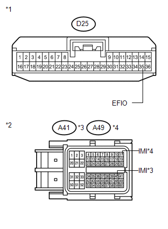
*1 |
Front view of wire harness connector (to Certification ECU (Smart Key ECU Assembly)) |
|
*2 |
Front view of wire harness connector (to ECM) |
|
*3 |
for 2GR-FE |
|
*4 |
for 1AR-FE |
| NG | |
REPAIR OR REPLACE HARNESS OR CONNECTOR |
|
|
3. |
CHECK CERTIFICATION ECU (SMART KEY ECU ASSEMBLY) |
(a) Reconnect the certification ECU (smart key ECU assembly) connector.
(b) Reconnect the ECM connector.
(c) Using an oscilloscope, check the waveform.
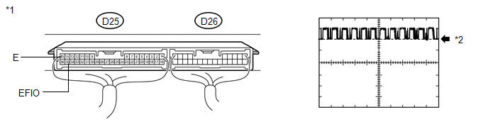
Waveform (Reference):
|
Item |
Content |
|---|---|
|
Terminal No. (Symbol) |
D25-35 (EFIO) - D25-15 (E) |
|
Tool Setting |
5 V/DIV., 100 msec./DIV. |
|
Condition |
Engine switch on (IG) |
OK:
Waveform is output normally (see illustration).
|
Result |
Proceed to |
|---|---|
|
NG |
A |
|
OK (for 2GR-FE) |
B |
|
OK (for 1AR-FE) |
C |
|
*1 |
Component with harness connected (Certification ECU (Smart Key ECU Assembly)) |
|
*2 |
GND |
| B | |
REPLACE ECM |
| C | |
REPLACE ECM |
|
|
4. |
REPLACE CERTIFICATION ECU (SMART KEY ECU ASSEMBLY) |
(a) Replace the certification ECU (smart key ECU assembly) (See page
).
|
|
5. |
KEY REGISTRATION |
(a) Register the key (See page ).
|
|
6. |
REGISTER ECU COMMUNICATION ID |
(a) Register the ECU communication ID (See page
).
|
|
7. |
CHECK DTC OUTPUT |
(a) Clear the DTCs (See page ).
(b) Recheck for DTCs (See page ).
OK:
DTC B279A is not output.
|
Result |
Proceed to |
|---|---|
|
OK |
A |
|
NG (for 2GR-FE) |
B |
|
NG (for 1AR-FE) |
C |
| A | |
END (CERTIFICATION ECU (SMART KEY ECU ASSEMBLY) WAS DEFECTIVE) |
| B | |
REPLACE ECM |
| C | |
REPLACE ECM |
 Diagnostic Trouble Code Chart
DIAGNOSTIC TROUBLE CODE CHART
HINT:
If a trouble code is stored during the DTC check, inspect the trouble areas listed
for that code. For details of the code, refer to the "See page" bel ...
 Short to GND in Immobiliser System Power Source Circuit (B278A)
DESCRIPTION
This DTC is stored when the engine switch power source supply line is open or
shorted.
DTC No.
DTC Detection Condition
Trouble Area
B2 ...
Other materials about Toyota Venza:
Front Blower Motor
Components
COMPONENTS
ILLUSTRATION
Installation
INSTALLATION
PROCEDURE
1. INSTALL FRONT BLOWER MOTOR SUB-ASSEMBLY
(a) Install the front blower motor sub-assembly with the 3 screws.
(b) Con ...
CD cannot be Ejected
PROCEDURE
1.
CHECK OPERATION
(a) Press the CD eject switch of the navigation receiver assembly for 10 seconds
or more and check that the CD is ejected.
OK:
CD is ejected.
NG
REPLACE NAVIGATION RECEIVER ...
Registration
REGISTRATION
CAUTION / NOTICE / HINT
NOTICE:
The Vehicle Identification Number (VIN) must be input into the replacement ECM.
HINT:
The VIN is a 17-digit alphanumeric vehicle identification number. The Techstream
is required to register the VIN.
PROCEDU ...

0.1679