Toyota Venza: Disassembly
DISASSEMBLY
PROCEDURE
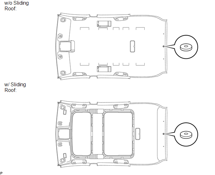
1. REMOVE NO. 2 ANTENNA CORD SUB-ASSEMBLY (w/o Sliding Roof)
.gif)
2. REMOVE NO. 2 ANTENNA CORD SUB-ASSEMBLY (w/ Sliding Roof)
3. REMOVE VANITY LIGHT ASSEMBLY
(a) Remove the vanity light assembly (See page
).
HINT:
Use the same procedure for the RH side and the LH side.
4. REMOVE FRONT SIDE RAIL SPACER LH (w/o Sliding Roof)
(a) Remove the front side rail spacer LH.
5. REMOVE FRONT SIDE RAIL SPACER RH (w/o Sliding Roof)
HINT:
Use the same procedure for the RH side and the LH side.
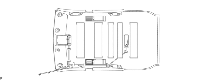
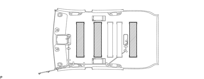
6. REMOVE NO. 3 ROOF SILENCER PAD (w/o Sliding Roof)
(a) Remove the 3 No. 3 roof silencer pads.
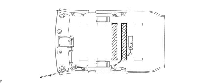
7. REMOVE NO. 2 ROOF SILENCER PAD (w/o Sliding Roof)
(a) Remove the 2 No. 2 roof silencer pads.
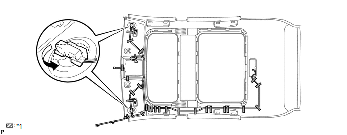
8. REMOVE NO. 1 ROOF WIRE (w/o Sliding Roof)
(a) Remove the adhesive tape.
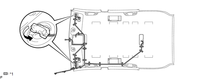 Text in Illustration
|
*1 |
Adhesive Tape |
- |
- |
(b) Turn the visor connectors counterclockwise approximately 90° and separate the connectors.
(c) Remove the No. 1 roof wire.
9. REMOVE NO. 1 ROOF WIRE (w/ Sliding Roof)
(a) Remove the adhesive tape.
(b) Turn the visor connectors counterclockwise approximately 90° and separate the connectors.
(c) Remove the No. 1 roof wire.
 Text in Illustration
|
*1 |
Adhesive Tape |
- |
- |
10. REMOVE NO. 14 ROOF SILENCER PAD
(a) Remove the No. 14 roof silencer pad.
 Components
COMPONENTS
ILLUSTRATION
ILLUSTRATION
ILLUSTRATION
ILLUSTRATION
ILLUSTRATION
ILLUSTRATION
ILLUSTRATION
ILLUSTRATION
ILLUSTRATION
ILLUSTRATION
ILLUSTRATION
ILLUSTRATION ...
 Removal
REMOVAL
PROCEDURE
1. REMOVE FRONT DOOR SCUFF PLATE LH
(a) Disengage the 3 clips, 7 claws and guide, and remove the front door
scuff plate LH.
...
Other materials about Toyota Venza:
Transmission Range Sensor Circuit Malfunction (PRNDL Input) (P0705)
DESCRIPTION
The park/neutral position switch detects the shift lever position and sends signals
to the TCM.
DTC No.
DTC Detection Condition
Trouble Area
P0705
(A) Any 2 or more signals of the fol ...
Ignition Hold Monitor Malfunction (B2271)
DESCRIPTION
This DTC is stored when a problem such as an open in the AM2 fuse, an open or
short in the wire harness between the fuse and power management control ECU, a short
in the IG output circuit inside the power management control ECU, a short betwee ...
Intake Air Control Valve Actuator(for Tcv)
Components
COMPONENTS
ILLUSTRATION
Removal
REMOVAL
PROCEDURE
1. REMOVE INTAKE MANIFOLD
(a) Remove the intake manifold (See page ).
2. REMOVE INTAKE AIR CONTROL VALVE ACTUATOR (for TCV)
(a) Remove the 2 bolts, intake air control valve actuator a ...

0.1554