Toyota Venza: Components
COMPONENTS
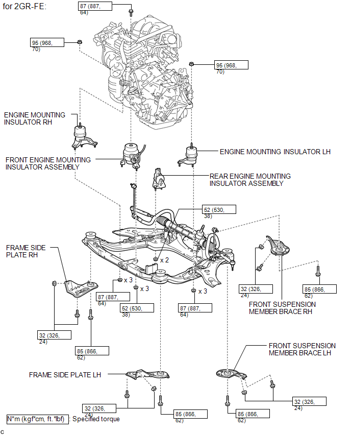
ILLUSTRATION
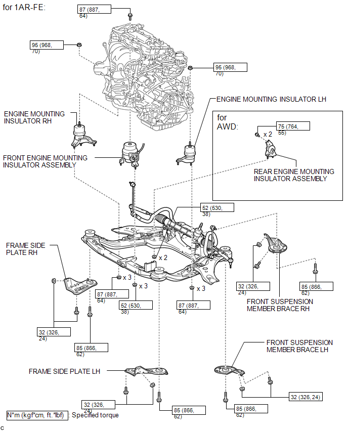
ILLUSTRATION
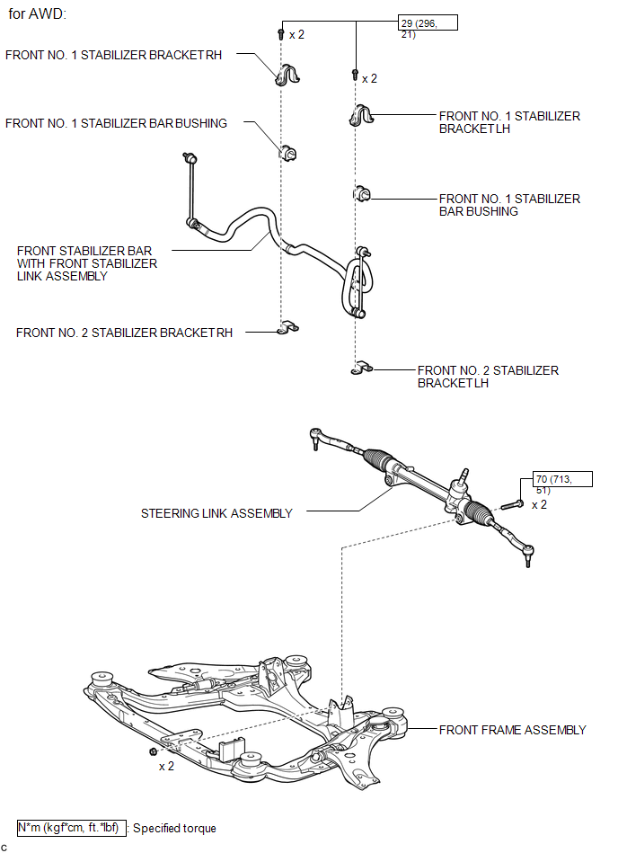
ILLUSTRATION
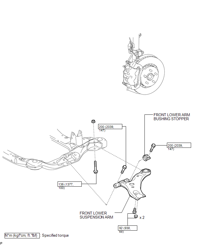
ILLUSTRATION

 Removal
REMOVAL
CAUTION / NOTICE / HINT
HINT:
Use the same procedure for the LH side and RH side.
The following procedure is for the LH side.
PROCEDURE
1. REMOVE ENGINE ASSEMBLY WITH TR ...
Other materials about Toyota Venza:
Dtc Check / Clear
DTC CHECK / CLEAR
NOTICE:
When the diagnosis system is changed from normal mode to check mode or vice versa,
all DTCs and freeze frame data recorded in normal mode are cleared. Before changing
modes, always check and make a note of DTCs and freeze frame ...
AWD Warning Light does not Come ON
DESCRIPTION
Refer to "AWD Warning Light Remains ON" (See page
).
WIRING DIAGRAM
Refer to "AWD Warning Light Remains ON" (See page
).
CAUTION / NOTICE / HINT
Check the condition of each related circuit connector before troubleshooti ...
Installation
INSTALLATION
PROCEDURE
1. INSTALL THERMOSTAT
(a) Install a new gasket to the thermostat.
(b) Install the thermostat with the jiggle valve facing upward.
HINT:
The jiggle valve may be set to within 10° on either side of the prescribed
...

0.1644