Toyota Venza: Removal
REMOVAL
CAUTION / NOTICE / HINT
CAUTION:
Some of these service operations affect the SRS airbag system. Read the precautionary
notices concerning the SRS airbag system before servicing the steering column (See
page .gif) ).
).
PROCEDURE
1. PRECAUTION
HINT:
(See page )
2. TURN FRONT WHEELS TO FACE STRAIGHT AHEAD
3. REMOVE FRONT WHEEL LH
4. REMOVE STEERING PAD
(See page )
5. REMOVE STEERING WHEEL ASSEMBLY
6. REMOVE DRIVER SIDE KNEE AIRBAG ASSEMBLY
(See page )
7. REMOVE LOWER STEERING COLUMN COVER
|
(a) Remove the 2 screws. |
|
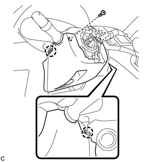
(b) Push the right and left sides of the lower steering column cover, and disengage the 2 claws to remove the lower steering column cover.
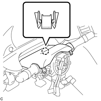
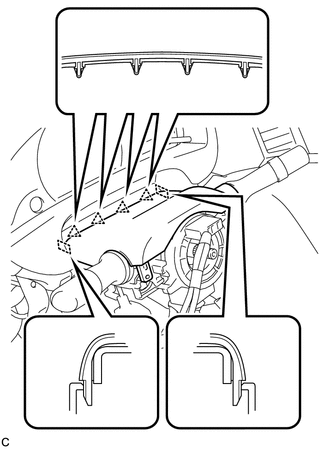
8. REMOVE UPPER STEERING COLUMN COVER
|
(a) Disengage the claw. |
|
|
(b) Disengage the 4 clips and 2 guides to remove the upper steering column cover. |
|
9. REMOVE TURN SIGNAL SWITCH ASSEMBLY WITH SPIRAL CABLE SUB-ASSEMBLY
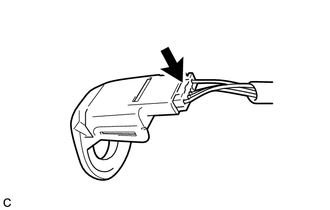
(a) Disconnect the connectors from the turn signal switch assembly with spiral cable sub-assembly.
|
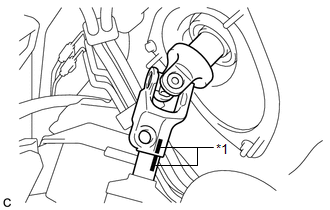
(b) Using pliers, expand the clamp. Text in Illustration
|
|
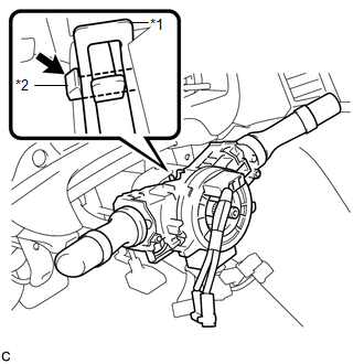
(c) While holding the clamp expanded, raise the claw using a screwdriver to disengage it, and then remove the turn signal switch assembly with spiral cable sub-assembly from the steering column assembly.
NOTICE:
- Do not replace the spiral cable with the battery connected and the ignition switch on.
- Do not rotate the spiral cable without the steering wheel with the battery connected and the ignition switch on.
- Ensure that the steering wheel is installed and aligned straight when inspecting the steering sensor.
- Do not remove the steering sensor from the spiral cable.
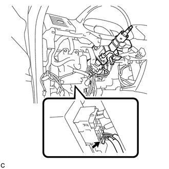
10. REMOVE TRANSPONDER KEY AMPLIFIER (w/o Smart Key System)
|
(a) Slide the transponder key amplifier to disengage the 2 claws as shown in the illustration. |
|
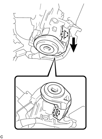
|
(b) Disconnect the connector and remove the transponder key amplifier. |
|
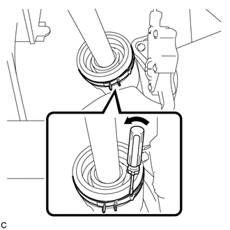
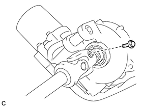
11. SEPARATE STEERING INTERMEDIATE SHAFT ASSEMBLY
|
(a) Using a screwdriver, loosen the clamp. |
|
|
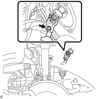
(b) Remove the bolt. NOTICE: Do not separate the steering intermediate shaft assembly from the power steering link assembly. |
|
|
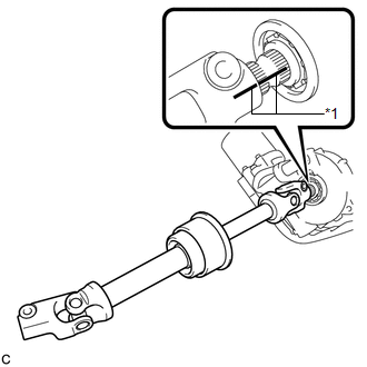
(c) Put matchmarks on the steering intermediate shaft assembly and the power steering link assembly. Text in Illustration
|
|
(d) Separate the steering intermediate shaft assembly from the power steering link assembly.
12. REMOVE STEERING POST ASSEMBLY
|
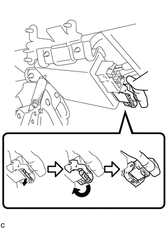
(a) Disconnect the connector from the power steering ECU assembly. |
|
|
(b) Disconnect the connector from the power steering ECU assembly. HINT: Pull out the lock of the lock lever, disengage the claw, and raise the lock lever to disconnect the connector as shown in the illustration. |
|
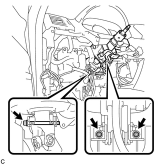
(c) Disconnect the connectors and disengage the wire harness clamps from the steering post assembly.
|
(d) Remove the bolt, 2 nuts, and the steering post assembly. |
|
13. REMOVE STEERING INTERMEDIATE SHAFT ASSEMBLY
|
(a) Remove the bolt and slide the steering intermediate shaft assembly. NOTICE: Do not separate the steering intermediate shaft assembly from the steering column assembly. |
|
|
(b) Put matchmarks on the steering intermediate shaft assembly and the steering column assembly. Text in Illustration
|
|
(c) Remove the steering intermediate shaft assembly from the steering column assembly.
 Components
COMPONENTS
ILLUSTRATION
ILLUSTRATION
ILLUSTRATION
ILLUSTRATION
ILLUSTRATION
...
 Disassembly
DISASSEMBLY
CAUTION / NOTICE / HINT
NOTICE:
When using a vise, do not overtighten it.
PROCEDURE
1. REMOVE STEERING LOCK ACTUATOR ASSEMBLY (w/ Smart Key System)
(a) Secure the steering column ass ...
Other materials about Toyota Venza:
Front Airbag Sensor LH Malfunction (B1615/14)
DESCRIPTION
The front airbag sensor LH circuit consists of the center airbag sensor assembly
and front airbag sensor LH.
The front airbag sensor LH detects impacts to the vehicle and sends signals to
the center airbag sensor assembly to determine if the ...
Removal
REMOVAL
PROCEDURE
1. REMOVE AIR CONDITIONING UNIT ASSEMBLY
(See page )
2. REMOVE NO. 1 FINISH PANEL MOUNTING BRACKET
3. REMOVE NO. 2 FINISH PANEL MOUNTING BRACKET
4. REMOVE NO. 3 AIR DUCT SUB-ASSEMBLY
5. REMOVE NO. 2 AIR DUCT SUB-ASSEMBLY
...
Registered Device cannot be Deleted
PROCEDURE
1.
DELETE OPERATION
(a) Check if a registered portable player can be deleted normally.
OK:
Registered portable player can be deleted normally.
OK
END
NG
PROCEED TO ...

0.129