Toyota Venza: Components
COMPONENTS
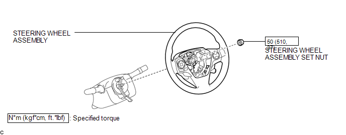
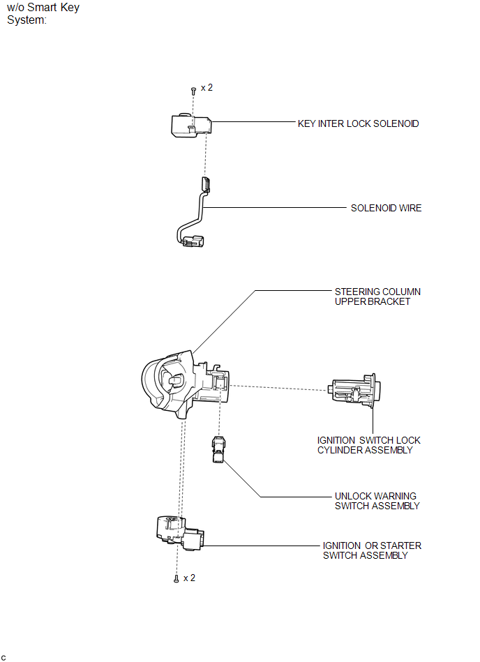
ILLUSTRATION
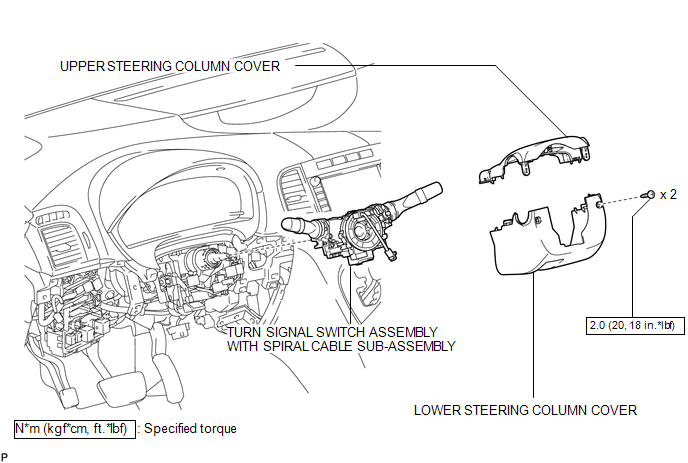
ILLUSTRATION
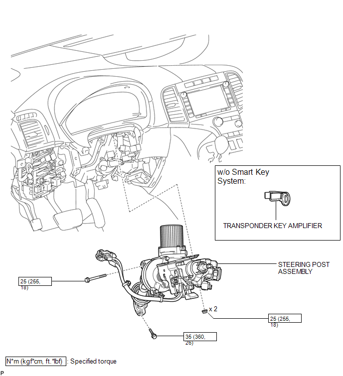
ILLUSTRATION
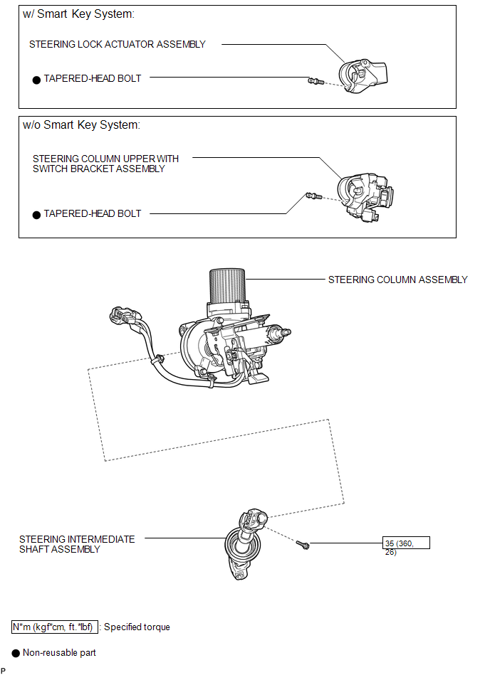
ILLUSTRATION
ILLUSTRATION

 Removal
REMOVAL
CAUTION / NOTICE / HINT
CAUTION:
Some of these service operations affect the SRS airbag system. Read the precautionary
notices concerning the SRS airbag system before servicing the steeri ...
Other materials about Toyota Venza:
Operation Check
OPERATION CHECK
1. CHECK PANEL & STEERING SWITCH
HINT:
The radio and display receiver assembly panel switches and steering
switches are checked in the following procedure.
Illustrations may differ from the actual vehicle screen depending ...
Antenna location and effective range
- Antenna location
1. Antennas outside cabin
2. Antennas inside cabin
3. Antenna outside luggage compartment
- Effective range (areas within which the electronic key is detected)
When locking or unlocking the doors The system can be operat ...
Removal
REMOVAL
PROCEDURE
1. REMOVE UPPER BACK WINDOW PANEL TRIM
2. REMOVE BACK DOOR PANEL TRIM ASSEMBLY
3. DISCONNECT POWER BACK DOOR ROD (w/ Power Back Door)
4. REMOVE BACK DOOR TRIM COVER LH (w/o Power Back Door)
5. REMOVE BACK DOOR TRIM COVER LH ...

0.1319