Toyota Venza: Power Management Control Ecu
Components
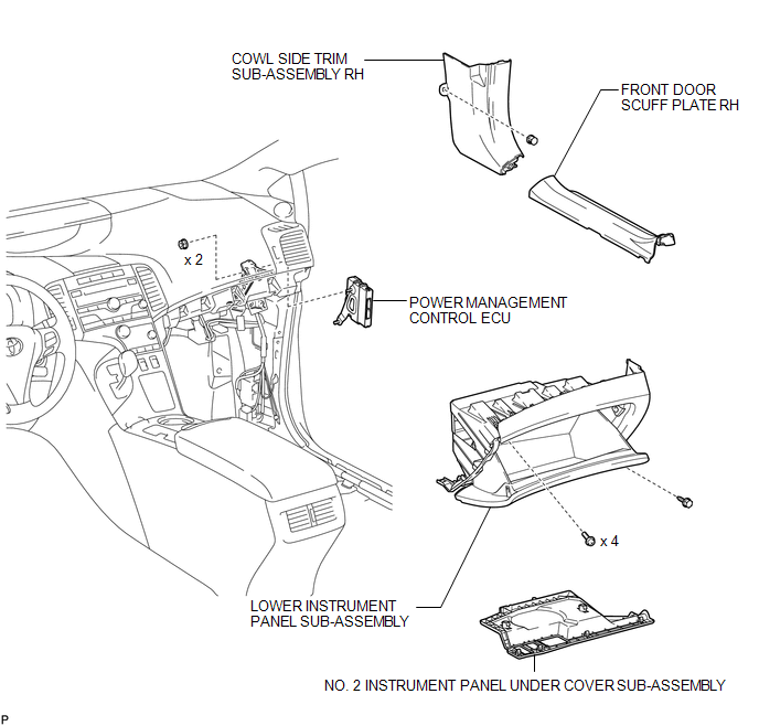
COMPONENTS
ILLUSTRATION
Removal
REMOVAL
PROCEDURE
1. REMOVE FRONT DOOR SCUFF PLATE RH
.gif)
2. REMOVE COWL SIDE TRIM SUB-ASSEMBLY RH
3. REMOVE NO. 2 INSTRUMENT PANEL UNDER COVER SUB-ASSEMBLY
4. REMOVE LOWER INSTRUMENT PANEL SUB-ASSEMBLY
5. REMOVE POWER MANAGEMENT CONTROL ECU
|
(a) Disconnect the 2 connectors. |
|
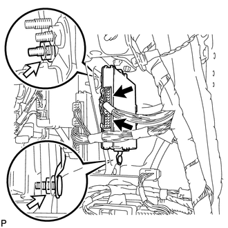
(b) Remove the 2 nuts and the power management control ECU.
Installation
INSTALLATION
PROCEDURE
1. INSTALL POWER MANAGEMENT CONTROL ECU
|
(a) Install the power management control ECU with the 2 nuts. |
|
.png)
(b) Connect the 2 connectors.
2. INSTALL LOWER INSTRUMENT PANEL SUB-ASSEMBLY
.gif)
3. INSTALL NO. 2 INSTRUMENT PANEL UNDER COVER SUB-ASSEMBLY
4. INSTALL COWL SIDE TRIM SUB-ASSEMBLY RH
5. INSTALL FRONT DOOR SCUFF PLATE RH
 Main Body Ecu
Components
COMPONENTS
ILLUSTRATION
Removal
REMOVAL
PROCEDURE
1. REMOVE UPPER INSTRUMENT PANEL
HINT:
Refer to the procedure up to Remove Upper Instrument Panel Sub-assembly (See
page ) ...

Other materials about Toyota Venza:
Disassembly
DISASSEMBLY
PROCEDURE
1. REMOVE SEAT ADJUSTER COVER CAP RH
(a) Using a screwdriver wrapped with protective tape, disengage the 3
claws and remove the seat adjuster cover cap RH.
Text in Illustration
*1
...
Installation
INSTALLATION
PROCEDURE
1. INSTALL FRONT NO. 3 SPEAKER ASSEMBLY (for 13 Speakers)
(a) Engage the 3 claws to install the front No. 3 speaker assembly.
2. INSTALL FRONT PILLAR GARNISH CORNER PIECE (for ...
Installation
INSTALLATION
CAUTION / NOTICE / HINT
HINT:
Use the same procedure for the LH side and RH side.
The following procedure is for the LH side.
If the sensor rotor needs to be replaced, replace it together with the
front drive shaft assembly. ...

0.1516