Toyota Venza: On-vehicle Inspection
ON-VEHICLE INSPECTION
CAUTION / NOTICE / HINT
HINT:
- Use the same procedure for the RH side and LH side.
- The procedure listed below is for the LH side.
PROCEDURE
1. REMOVE FRONT WHEEL
2. SEPARATE FRONT DISC BRAKE CALIPER ASSEMBLY
.gif)
3. REMOVE FRONT DISC
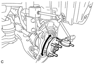
4. INSPECT FRONT AXLE HUB BEARING LOOSENESS
|
(a) Using a dial indicator, check for looseness near the center of the front axle hub. Maximum looseness: 0.05 mm (0.00196 in.) NOTICE: Ensure that the dial indicator is set perpendicular to the measurement surface. If the looseness exceeds the maximum, replace the front axle hub bearing. |
|

5. INSPECT FRONT AXLE HUB RUNOUT
|
(a) Using a dial indicator, check for runout on the surface of the axle hub outside the hub bolt. Maximum runout: 0.05 mm (0.00196 in.) NOTICE: Ensure that the dial indicator is set perpendicular to the measurement surface. If the runout exceeds the maximum, replace the front axle hub sub-assembly. |
|
6. INSTALL FRONT DISC
7. INSTALL FRONT DISC BRAKE CALIPER ASSEMBLY
8. INSTALL FRONT WHEEL
Torque:
103 N·m {1050 kgf·cm, 76 ft·lbf}
 Components
COMPONENTS
ILLUSTRATION
ILLUSTRATION
...
 Removal
REMOVAL
CAUTION / NOTICE / HINT
HINT:
Use the same procedure for the RH side and LH side.
The procedure listed below is for the LH side.
PROCEDURE
1. REMOVE FRONT WHEEL
2. REMO ...
Other materials about Toyota Venza:
On-vehicle Inspection
ON-VEHICLE INSPECTION
PROCEDURE
1. INSPECT CENTER AIRBAG SENSOR ASSEMBLY (VEHICLE NOT INVOLVED IN COLLISION)
(a) Perform a diagnostic system check (See page
).
2. INSPECT CENTER AIRBAG SENSOR ASSEMBLY (VEHICLE INVOLVED IN COLLISION AND AIRBAG
HAS NOT D ...
Reassembly
REASSEMBLY
PROCEDURE
1. INSTALL REAR DRIVE SHAFT DUST COVER
(a) Using SST and a steel plate, install a new rear drive shaft dust
cover to the rear drive shaft inboard joint assembly.
Text in Illustration
*1
...
Diagnostic Trouble Code Chart
DIAGNOSTIC TROUBLE CODE CHART
ACTIVE TORQUE CONTROL 4WD SYSTEM
DTC Code
Detection Item
Trouble Area
See page
C1241/94
Low Power Supply Voltage
1. Battery
2. ECU-IG1 fuse
...

0.1381