Toyota Venza: Removal
REMOVAL
CAUTION / NOTICE / HINT
CAUTION:
- Wear protective gloves when removing the exhaust pipe.
- The exhaust pipe is extremely hot immediately after the engine has stopped.
- Confirm that the exhaust pipe has cooled down before removing it.
PROCEDURE
1. REMOVE NO. 1 ENGINE UNDER COVER
2. REMOVE NO. 2 ENGINE UNDER COVER
3. REMOVE FRONT EXHAUST PIPE ASSEMBLY
|
(a) Disconnect the heated oxygen sensor connector. |
|
|
(b) Remove the 4 bolts, 2 compression springs and front exhaust pipe assembly from the exhaust manifold converter sub-assembly and center exhaust pipe assembly. |
|
(c) Remove the 2 gaskets from the exhaust manifold converter sub-assembly and center exhaust pipe assembly.
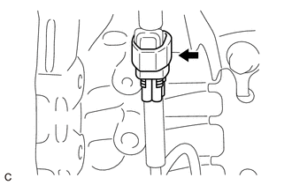
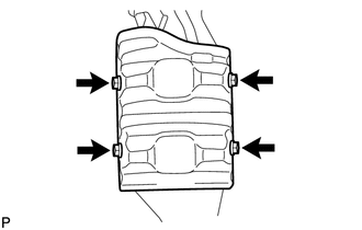
4. REMOVE AIR FUEL RATIO SENSOR
.gif)
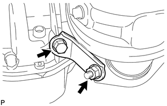
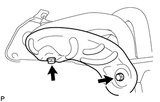
5. REMOVE MANIFOLD STAY
|
(a) Remove the bolt, nut and manifold stay from the exhaust manifold converter sub-assembly and stiffening crankcase assembly. |
|
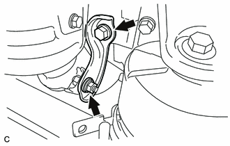
6. REMOVE NO. 2 MANIFOLD STAY
|
(a) Remove the bolt, nut and No. 2 manifold stay from the exhaust manifold converter sub-assembly and stiffening crankcase assembly. |
|
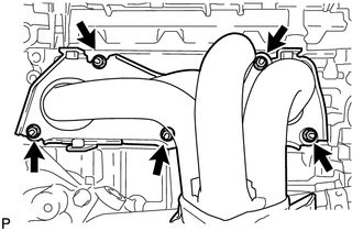
7. REMOVE NO. 1 EXHAUST MANIFOLD HEAT INSULATOR
|
(a) Remove the 4 bolts and No. 1 exhaust manifold heat insulator from the exhaust manifold converter sub-assembly. |
|
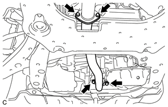
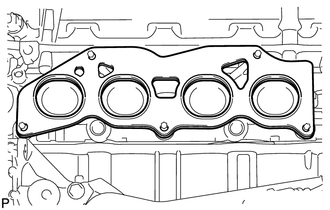
8. REMOVE EXHAUST MANIFOLD CONVERTER SUB-ASSEMBLY
|
(a) Remove the 5 nuts and exhaust manifold converter sub-assembly from the cylinder head sub-assembly. |
|
|
(b) Remove the gasket from the cylinder head sub-assembly. |
|
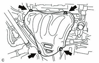
9. REMOVE NO. 2 EXHAUST MANIFOLD HEAT INSULATOR
|
(a) Remove the 2 bolts and No. 2 exhaust manifold heat insulator from the exhaust manifold converter sub-assembly. |
|
10. REMOVE NO. 1 MANIFOLD CONVERTER INSULATOR
|
(a) Remove the 4 bolts and No. 1 manifold converter insulator from the exhaust manifold converter sub-assembly. |
|
 Components
COMPONENTS
ILLUSTRATION
ILLUSTRATION
...
 Installation
INSTALLATION
PROCEDURE
1. INSTALL NO. 1 MANIFOLD CONVERTER INSULATOR
(a) Install the No. 1 manifold converter insulator to the exhaust manifold
converter sub-assembly with the 4 bolt ...
Other materials about Toyota Venza:
Problem Symptoms Table
PROBLEM SYMPTOMS TABLE
HINT:
Use the table below to help determine the cause of problem symptoms.
If multiple suspected areas are listed, the potential causes of the symptoms
are listed in order of probability in the "Suspected Area" ...
Power Mirror Control System(w/o Memory)
Parts Location
PARTS LOCATION
ILLUSTRATION
Problem Symptoms Table
PROBLEM SYMPTOMS TABLE
HINT:
Use the table below to help determine the cause of problem symptoms. If multiple
suspected areas are listed, the potential causes of the symptoms are l ...
Moon roof
Use the overhead switches to open, close, and tilt the moon roof up and down.
- Opening and closing
1. Open
The moon roof stops slightly before the fully open position to reduce wind noise.
Move the switch backward again to fully open.
2. Close ( ...

0.1153