Toyota Venza: Combination Meter ECU Communication Stop Mode
DESCRIPTION
|
Detection Item |
Symptom |
Trouble Area |
|---|---|---|
|
Combination Meter ECU Communication Stop Mode |
|
|
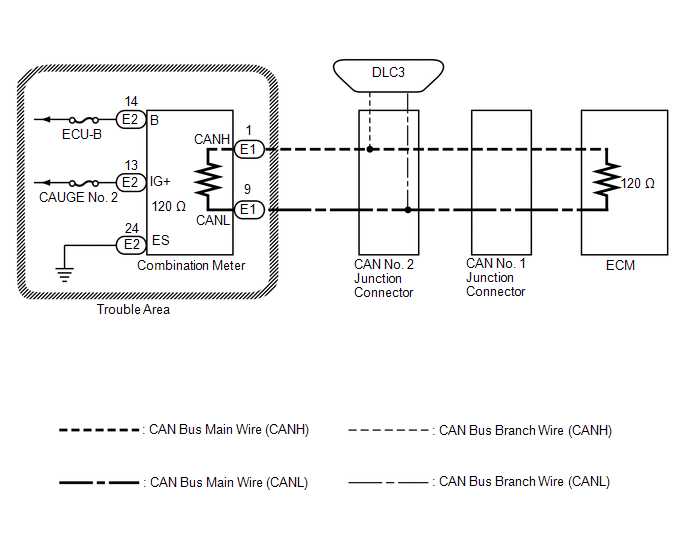
WIRING DIAGRAM
CAUTION / NOTICE / HINT
NOTICE:
- Turn the ignition switch off before measuring the resistances between CAN bus main wires and between CAN bus branch wires.
- Turn the ignition switch off before inspecting CAN bus wires for a ground short.
- After the ignition switch is turned off, check that the key reminder warning system and light reminder warning system are not operating.
- Before measuring the resistance, leave the vehicle as is for at least 1 minute and do not operate the ignition switch, any other switches or the doors. If any doors need to be opened in order to check connectors, open the doors and leave them open.
HINT:
- Operating the ignition switch, any other switches or a door triggers related ECU and sensor communication on the CAN. This communication will cause the resistance value to change.
- Even after DTCs are cleared, if a DTC is stored again after driving the vehicle for a while, the malfunction may be occurring due to vibration of the vehicle. In such a case, wiggling the ECUs or wire harness while performing the inspection below may help determine the cause of the malfunction.
PROCEDURE
|
1. |
CHECK CAN BUS WIRE FOR DISCONNECTION (COMBINATION METER MAIN WIRE) |
(a) Turn the ignition switch off.
|
(b) Disconnect the connector of the combination meter. Text in Illustration
|
|
(c) Measure the resistance according to the value(s) in the table below.
Standard Resistance:
|
Tester Connection |
Switch Condition |
Specified Condition |
|---|---|---|
|
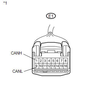
E1-1 (CANH) - E1-9 (CANL) |
ignition switch off |
108 to 132 Ω |
| NG | .gif) |
REPAIR OR REPLACE CAN BUS MAIN WIRE OR CONNECTOR (COMBINATION METER MAIN WIRE) |
|
.gif)
|
2. |
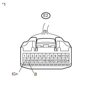
CHECK HARNESS AND CONNECTOR (POWER SOURCE TERMINAL) |
|
(a) Measure the voltage according to the value(s) in the table below. Standard Voltage:
|
|
| NG | |
REPAIR OR REPLACE HARNESS OR CONNECTOR (POWER SOURCE CIRCUIT) |
|
|
3. |
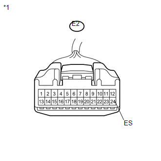
CHECK HARNESS AND CONNECTOR (GROUND TERMINAL) |
|
(a) Turn the ignition switch off. |
|
(b) Measure the resistance according to the value(s) in the table below.
Standard Resistance:
|
Tester Connection |
Condition |
Specified Condition |
|---|---|---|
|
E2-24 (ES) - Body ground |
Always |
Below 1 Ω |
|
*1 |
Front view of wire harness connector (to Combination Meter) |
| OK | |
REPLACE COMBINATION METER |
| NG | |
REPAIR OR REPLACE HARNESS OR CONNECTOR (GROUND CIRCUIT) |
 Certification ECU Communication Stop Mode
DESCRIPTION
Detection Item
Symptom
Trouble Area
Certification ECU Communication Stop Mode
"Smart Access/Smart Key/Wireless ...
 Center Airbag Sensor Communication Stop Mode
DESCRIPTION
Detection Item
Symptom
Trouble Area
Center Airbag Sensor Communication Stop Mode
"SRS Airbag" is not disp ...
Other materials about Toyota Venza:
Precaution
PRECAUTION
1. PRECAUTION FOR DISCONNECTING CABLE FROM NEGATIVE BATTERY TERMINAL
NOTICE:
When disconnecting the cable from the negative (-) battery terminal, initialize
the following system after the terminal is reconnected:
System Name
...
Problem Symptoms Table
PROBLEM SYMPTOMS TABLE
Use the table below to help determine the cause of problem symptoms.
If multiple suspected areas are listed, the potential causes of the symptoms
are listed in order of probability in the "Suspected Area" column ...
Pressure Control Solenoid "A" Performance (Shift Solenoid Valve SL1) (P0746)
SYSTEM DESCRIPTION
The TCM uses the vehicle speed signal and signals from the transmission speed
sensors (NC, NT) to detect the actual gear (1st, 2nd, 3rd, 4th, 5th or 6th gear).
Then the TCM compares the actual gear with the shift schedule in the TCM memo ...

0.1421