Toyota Venza: Installation
INSTALLATION
PROCEDURE
1. INSTALL NO. 1 MANIFOLD CONVERTER INSULATOR
|
(a) Install the No. 1 manifold converter insulator to the exhaust manifold converter sub-assembly with the 4 bolts. Torque: 12 N·m {122 kgf·cm, 9 ft·lbf} |
|
.png)
2. INSTALL NO. 2 EXHAUST MANIFOLD HEAT INSULATOR
|
(a) Install the No. 2 exhaust manifold heat insulator to the exhaust manifold converter sub-assembly with the 2 bolts. Torque: 12 N·m {122 kgf·cm, 9 ft·lbf} |
|
.png)
3. INSTALL EXHAUST MANIFOLD CONVERTER SUB-ASSEMBLY
|
(a) Install a new gasket onto the cylinder head sub-assembly. |
|
.png)
|
(b) Temporarily install the exhaust manifold converter sub-assembly to the cylinder head sub-assembly with the 5 nuts. |
|
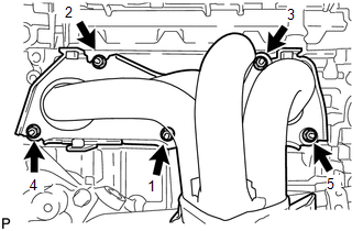
(c) Tighten the 5 nuts in the order shown in the illustration.
Torque:
35 N·m {357 kgf·cm, 26 ft·lbf}
4. INSTALL NO. 1 EXHAUST MANIFOLD HEAT INSULATOR
|
(a) Install the No. 1 exhaust manifold heat insulator to the exhaust manifold converter sub-assembly with the 4 bolts. Torque: 12 N·m {122 kgf·cm, 9 ft·lbf} |
|
.png)
5. INSTALL NO. 2 MANIFOLD STAY
|
(a) Install the No. 2 manifold stay to the exhaust manifold converter sub-assembly and stiffening crankcase assembly with the bolt and nut. Torque: 43 N·m {438 kgf·cm, 32 ft·lbf} |
|
.png)
6. INSTALL MANIFOLD STAY
|
(a) Install the manifold stay to the exhaust manifold converter sub-assembly and stiffening crankcase assembly with the bolt and nut. Torque: 43 N·m {438 kgf·cm, 32 ft·lbf} |
|
.png)
7. INSTALL AIR FUEL RATIO SENSOR
.gif)
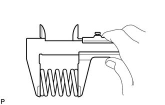
8. INSTALL FRONT EXHAUST PIPE ASSEMBLY
|
(a) Using a vernier caliper, measure the free length of the compression spring. Minimum Free Length: 41.5 mm (1.63 in.) If the length is less than the minimum, replace the compression spring. |
|
(b) Temporarily install a new gasket to the exhaust manifold converter sub-assembly.
|
(c) Using a plastic hammer and wooden block, tap in the gasket until its surface is flush with the exhaust manifold converter sub-assembly. Text in Illustration
NOTICE:
|
|
(d) Install a new gasket to the center exhaust pipe assembly.
|
(e) Install the front exhaust pipe assembly to the exhaust manifold converter sub-assembly and center exhaust pipe assembly with the 2 compression springs and 4 bolts. Torque: 43 N·m {438 kgf·cm, 32 ft·lbf} |
|
.png)
|
(f) Connect the heated oxygen sensor connector. |
|
.png)
9. INSPECT FOR EXHAUST GAS LEAK
10. INSTALL NO. 2 ENGINE UNDER COVER
11. INSTALL NO. 1 ENGINE UNDER COVER
 Removal
REMOVAL
CAUTION / NOTICE / HINT
CAUTION:
Wear protective gloves when removing the exhaust pipe.
The exhaust pipe is extremely hot immediately after the engine has stopped.
...
 Exhaust Pipe
...
Other materials about Toyota Venza:
Inspection
INSPECTION
PROCEDURE
1. INSPECT PARKING BRAKE SWITCH ASSEMBLY
(a) Measure the resistance according to the value(s) in the table below.
Standard Resistance:
Tester Connection
Switch Condition
...
System Diagram
SYSTEM DIAGRAM
Input and Output Signal of Each ECU
Transmitting ECU (transmitter)
Receiving ECU
Signal
Communication Method
Power management Control ECU
Steering Lock ECU (Steering Lock ...
Removal
REMOVAL
CAUTION / NOTICE / HINT
HINT:
Use the same procedure for the RH side and LH side.
The procedure listed below is for the LH side.
PROCEDURE
1. REMOVE REAR WHEEL
2. REMOVE DECK SIDE TRIM
(a) Disengage the 5 claws, and ...

0.1344