Toyota Venza: Components
COMPONENTS
ILLUSTRATION
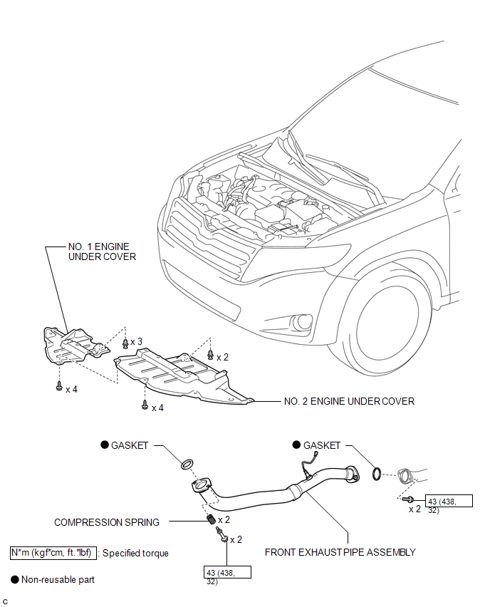
ILLUSTRATION
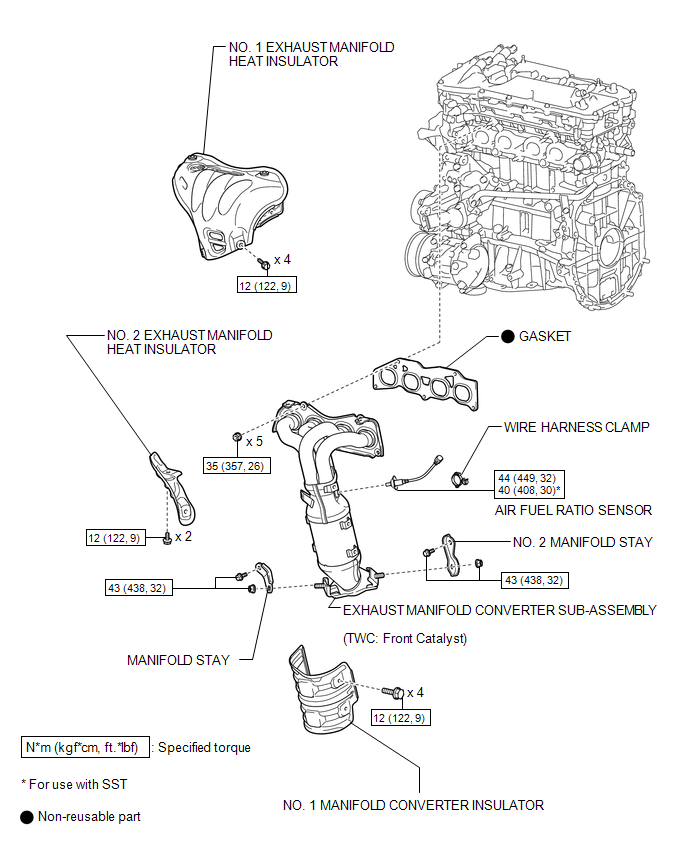
 Exhaust Manifold
...
 Removal
REMOVAL
CAUTION / NOTICE / HINT
CAUTION:
Wear protective gloves when removing the exhaust pipe.
The exhaust pipe is extremely hot immediately after the engine has stopped.
...
Other materials about Toyota Venza:
Installation
INSTALLATION
PROCEDURE
1. INSTALL GENERATOR ASSEMBLY
(a) Install the wire harness clamp with the bolt.
Torque:
8.4 N·m {86 kgf·cm, 74 in·lbf}
(b) Install the 2 bolts.
Torque: ...
Power Back Door Main Switch
Components
COMPONENTS
ILLUSTRATION
Inspection
INSPECTION
PROCEDURE
1. INSPECT POWER BACK DOOR MAIN SWITCH
(a) Check that the switch function.
(1) Measure the resistance according to the value(s) in the table below.
Standard Resistance:
...
Components
COMPONENTS
ILLUSTRATION
ILLUSTRATION
ILLUSTRATION
ILLUSTRATION
ILLUSTRATION
...
© 2016-2026 Copyright www.tovenza.com

0.1383
0.1383