Toyota Venza: Removal
REMOVAL
CAUTION / NOTICE / HINT
HINT:
Perform "Inspection After Repair" after replacing the fuel injector assembly
(See page .gif) ).
).
PROCEDURE
1. DISCHARGE FUEL SYSTEM PRESSURE
(a) Discharge fuel system pressure (See page
).
2. DISCONNECT CABLE FROM NEGATIVE BATTERY TERMINAL
NOTICE:
When disconnecting the cable, some systems need to be initialized after the cable
is reconnected (See page ).
3. REMOVE WINDSHIELD WIPER MOTOR AND LINK ASSEMBLY
(a) Remove the windshield wiper motor and link assembly (See page
).
4. REMOVE OUTER COWL TOP PANEL
5. REMOVE NO. 1 ENGINE COVER SUB-ASSEMBLY
6. REMOVE NO. 1 VACUUM SWITCHING VALVE ASSEMBLY
7. REMOVE AIR CLEANER CAP SUB-ASSEMBLY
8. DISCONNECT FUEL TUBE SUB-ASSEMBLY
(a) Remove the No. 1 fuel pipe clamp.
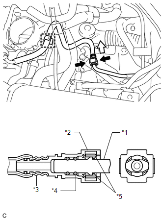
(b) Pinch the retainer of the fuel tube connector, and then pull the fuel tube connector off of the fuel pipe.
 Text in Illustration
|
*1 |
Fuel Pipe |
|
*2 |
Fuel Tube Connector |
|
*3 |
Nylon Tube |
|
*4 |
O-ring |
|
*5 |
Retainer |
.png) |
Pinch |
.png) |
Pull |
NOTICE:
- Check for foreign matter on the fuel tube around the fuel tube connector. Clean it if necessary. Foreign matter can affect the ability of the O-ring to seal the fuel tube connector and fuel pipe.
- Do not use any tools to separate the fuel tube connector and fuel pipe.
- Do not forcibly bend, kink or twist the nylon tube.
- Keep the connector and pipe free from foreign matter.
- If the fuel tube connector and fuel pipe are stuck, push and pull to release them.
- Cover the fuel tube connector and fuel pipe with plastic bags to prevent damage and contamination.
(c) Remove the fuel tube sub-assembly from the fuel hose clamp.
9. REMOVE VACUUM SWITCHING VALVE ASSEMBLY (for ACIS)
10. DISCONNECT WIRE HARNESS
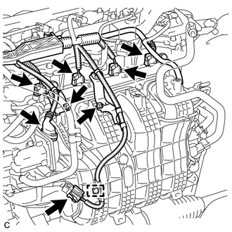
(a) Disconnect the 4 fuel injector connectors.
(b) Disconnect the 2 connectors.
(c) Remove the 2 bolts and separate the 2 wire harness brackets.
(d) Disengage the clamp to disconnect the wire harness.
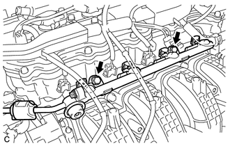
11. REMOVE FUEL DELIVERY PIPE SUB-ASSEMBLY
|
(a) Remove the 2 bolts, and then remove the fuel delivery pipe together with the 4 fuel injectors. NOTICE: Be careful not to drop the fuel injectors when removing the fuel delivery pipe. |
|
|
(b) Remove the 2 fuel delivery spacers from the cylinder head. |
|
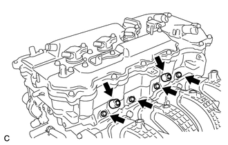
(c) Remove the 4 injector vibration insulators from the cylinder head.
12. REMOVE FUEL INJECTOR ASSEMBLY
|
(a) Pull the 4 fuel injectors out of the fuel delivery pipe. |
|
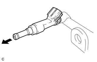
(b) Remove the O-ring from each fuel injector.
(c) For reinstallation, attach a tag or label to each injector shaft.
NOTICE:
Prevent entry of foreign matter by covering the fuel injectors with plastic bags.
 Components
COMPONENTS
ILLUSTRATION
ILLUSTRATION
ILLUSTRATION
...
 Inspection
INSPECTION
PROCEDURE
1. INSPECT FUEL INJECTOR ASSEMBLY
(a) Measure the resistance according to the value(s) in the table below.
Standard Resistance:
Tester Connec ...
Other materials about Toyota Venza:
Removal
REMOVAL
CAUTION / NOTICE / HINT
NOTICE:
When disconnecting the steering intermediate shaft assembly and pinion shaft
of steering gear assembly, be sure to place matchmarks before servicing.
PROCEDURE
1. PLACE FRONT WHEELS FACING STRAIGHT AHEAD
2. SECUR ...
Horn System
Precaution
PRECAUTION
NOTICE:
When disconnecting the cable from the negative (-) battery terminal, initialize
the following system after the cable is reconnected.
System Name
See Procedure
Back Door Closer System
...
Removal
REMOVAL
PROCEDURE
1. PRECAUTION
(See page )
2. ALIGN FRONT WHEELS FACING STRAIGHT AHEAD
3. DISCONNECT CABLE FROM NEGATIVE BATTERY TERMINAL
CAUTION:
Wait at least 90 seconds after disconnecting the cable from the negative (-)
battery terminal to disab ...

0.1584