Toyota Venza: Inspection
INSPECTION
PROCEDURE
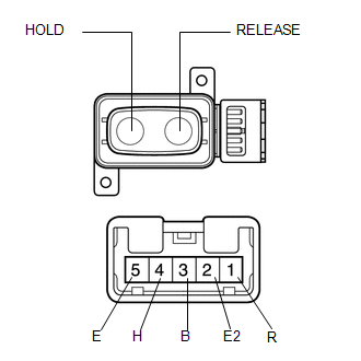
1. INSPECT DRIVER SIDE LUMBAR SWITCH
|
(a) Measure the resistance between the terminals when the switch is operated. Standard Resistance:
If the result is not as specified, replace the switch. |
|
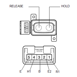
2. INSPECT FRONT PASSENGER SIDE LUMBAR SWITCH
|
(a) Measure the resistance between the terminals when the switch is operated. Standard Resistance:
If the result is not as specified, replace the switch. |
|
 Removal
REMOVAL
PROCEDURE
1. REMOVE FRONT SEAT HEADREST ASSEMBLY
2. REMOVE FRONT SEAT REAR OUTER TRACK COVER
3. REMOVE FRONT SEAT REAR INNER TRACK COVER
4. REMOVE FRONT SEAT ASSEMBLY
5. REMOVE ...
 Installation
INSTALLATION
PROCEDURE
1. INSTALL FRONT POWER SEAT LUMBAR SWITCH
(a) Install the front power seat lumbar switch with the 2 screws.
2. INST ...
Other materials about Toyota Venza:
Registration
REGISTRATION
PROCEDURE
1. REGISTER TRANSMITTER CODE
HINT:
The vehicles garage door opener system records transmitter codes for
systems such as garage doors, gates, door locks, home lighting systems,
security systems or other transmitter-cod ...
Lost Communication with ECM / PCM "A" (U0100)
DESCRIPTION
The engine control unit communicates with the TCM using the Controller Area Network
(CAN).
If there is a problem in this communication, the TCM sets a DTC.
DTC No.
DTC Detection Condition
Trouble Area
...
CD cannot be Ejected
PROCEDURE
1.
CHECK OPERATION
(a) Press the disc eject switch of the radio and display receiver assembly for
5 seconds or more and check that the CD is ejected.
OK:
CD is ejected.
NG
REPLACE RADIO AND D ...

0.1215