Toyota Venza: Components
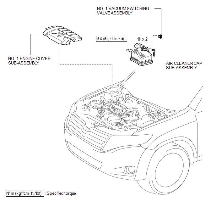
COMPONENTS
ILLUSTRATION
.png)
ILLUSTRATION
ILLUSTRATION
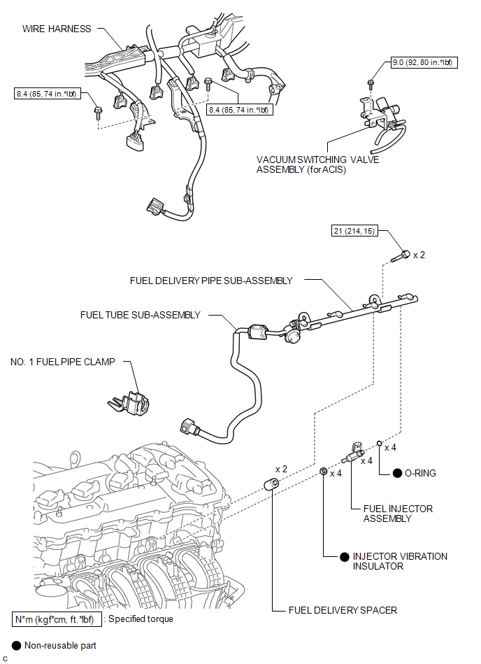
 Fuel Injector
...
 Removal
REMOVAL
CAUTION / NOTICE / HINT
HINT:
Perform "Inspection After Repair" after replacing the fuel injector assembly
(See page ).
PROCEDURE
1. DISCHARGE FUEL SYSTEM PRESSURE
(a) Disch ...
Other materials about Toyota Venza:
Replacement
REPLACEMENT
CAUTION / NOTICE / HINT
HINT:
Use the same procedure for the RH side and LH side.
The procedure listed below is for the LH side.
PROCEDURE
1. DRAIN DIFFERENTIAL OIL
2. REMOVE REAR WHEEL
3. REMOVE CENTER EXHAUST PIPE ASSE ...
Main Body Ecu
Components
COMPONENTS
ILLUSTRATION
Removal
REMOVAL
PROCEDURE
1. REMOVE UPPER INSTRUMENT PANEL
HINT:
Refer to the procedure up to Remove Upper Instrument Panel Sub-assembly (See
page ).
2. REMOVE MAIN BODY ECU (DRIVER SIDE JUNCTION BLOCK ASSEM ...
Diagnosis System
DIAGNOSIS SYSTEM
1. DESCRIPTION
When troubleshooting a vehicle with a diagnosis system, the only difference from
the usual troubleshooting procedure is connecting the Techstream to the vehicle
and reading various data output from the vehicle's skid c ...

0.1712