Toyota Venza: Low Power Supply Voltage (C1241/94)
DESCRIPTION
If a malfunction in the power source circuit occurs, or a malfunction in communication with the skid control ECU or in a speed sensor occurs, the AWD control ECU will prohibit operations by the fail-safe function.
|
DTC No. |
DTC Detection Condition |
Trouble Area |
|---|---|---|
|
C1241/94 |
|
|
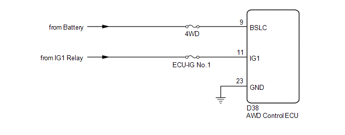
WIRING DIAGRAM
CAUTION / NOTICE / HINT
NOTICE:
Inspect the fuses for circuits related to this system before performing the following inspection procedure.
HINT:
Check the condition of each related circuit connector before troubleshooting
(See page .gif) ).
).
PROCEDURE
|
1. |
CHECK FOR DTC (CAN COMMUNICATION SYSTEM AND BRAKE CONTROL SYSTEM) |
(a) Check if the CAN communication system DTC is output (See page
).
(b) Start the engine.
(c) Drive the vehicle, accelerate to a speed of 3 km/h (2 mph) or more, and check
if the speed sensor DTC (brake control system DTC) is output (See page
).
|
Result |
Proceed to |
|---|---|
|
Neither CAN communication system DTC nor speed sensor DTC (brake control system DTC) is output |
A |
|
CAN communication system DTC is output |
B |
|
Speed sensor DTC (brake control system DTC) is output |
C |
| B | .gif) |
REPAIR CIRCUIT INDICATOR BY OUTPUT CODE (CAN COMMUNICATION SYSTEM) |
| C | |
REPAIR CIRCUIT INDICATOR BY OUTPUT CODE (BRAKE CONTROL SYSTEM) |
|
.gif)
|
2. |
INSPECT BATTERY |
(a) Check the battery voltage.
Standard Voltage:
11 to 14 V
|
Result |
Proceed to |
|---|---|
|
OK |
A |
|
NG (2GR-FE) |
B |
|
NG (1AR-FE) |
C |
| B | |
INSPECT CHARGING SYSTEM (2GR-FE) |
| C | |
INSPECT CHARGING SYSTEM (1AR-FE) |
|
|
3. |
CHECK WIRE HARNESS (AWD CONTROL ECU - BATTERY) |
(a) Disconnect the ECU connector.
(b) Measure the voltage of the wire harness side connector.
Standard Voltage:
|
Tester Connection |
Switch Condition |
Specified Condition |
|---|---|---|
|
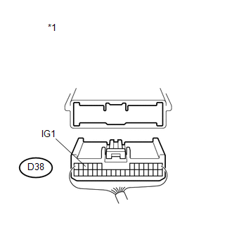
D38-11 (IG1) - Body Ground |
Ignition switch ON |
11 to 14 V |
|
*1 |
Rear view of wire harness connector (to AWD Control ECU) |
| NG | |
REPAIR OR REPLACE HARNESS OR CONNECTOR |
|
|
4. |
CHECK WIRE HARNESS (AWD CONTROL ECU - BODY GROUND) |
(a) Disconnect the ECU connector.
(b) Measure the resistance of the wire harness side connector.
Standard Resistance:
|
Tester Connection |
Condition |
Specified Condition |
|---|---|---|
|
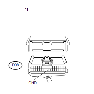
D38-23 (GND) - Body Ground |
Always |
Below 1 Ω |
|
*1 |
Rear view of wire harness connector (to AWD Control ECU) |
| NG | |
REPAIR OR REPLACE HARNESS OR CONNECTOR |
|
|
5. |
RECONFIRM DTC |
(a) Clear the DTC (See page ).
(b) Start the engine.
(c) Drive the vehicle, accelerate to a speed of 3 km/h (2 mph or more, and check if the same DTC is output.
|
Result |
Proceed to |
|---|---|
|
DTC is output |
A |
|
DTC is not output |
B |
HINT:
Reinstall the sensor, connectors, etc. and restore the vehicle to its prior condition before rechecking DTCs.
| A | |
REPLACE AWD CONTROL ECU |
| B | |
CHECK INTERMITTENT PROBLEMS |
 Diagnostic Trouble Code Chart
DIAGNOSTIC TROUBLE CODE CHART
ACTIVE TORQUE CONTROL 4WD SYSTEM
DTC Code
Detection Item
Trouble Area
See page
C1241/94
Low Powe ...
 Control Module Communication Bus OFF (U0073/86,U0100/85,U0129/83)
DESCRIPTION
The AWD control ECU inputs the signals sent from the ECM and skid control
ECU via the CAN communication system.
When DTCs indicating a CAN communication system malfunction ...
Other materials about Toyota Venza:
Unlocking and locking the doors
►Front door handle
Grip the driver’s door handle to unlock the door. Grip the passenger’s door handle
to unlock all the doors.* Make sure to touch the sensor on the back of the handle.
The doors cannot be unlocked for 3 seconds after the doors ...
On-vehicle Inspection
ON-VEHICLE INSPECTION
CAUTION / NOTICE / HINT
CAUTION:
Be sure to follow the correct removal and installation procedures of the front
airbag sensor.
PROCEDURE
1. INSPECT FRONT AIRBAG SENSOR (VEHICLE NOT INVOLVED IN COLLISION)
(a) Perform a diagnostic s ...
Inspection
INSPECTION
PROCEDURE
1. INSPECT FRONT DRIVE SHAFT ASSEMBLY
(a) Check whether the drive shaft dimensions are within the following
specifications.
Text in Illustration
*A
LH
*B
...

0.1227