Toyota Venza: Registration
REGISTRATION
CAUTION / NOTICE / HINT
HINT:
- Register a new recognition code when replacing the door control transmitter or the door control receiver.
- Add mode is used to retain the already registered codes while registering a new recognition code. This mode is used when adding a transmitter.
- Rewrite mode is used to clear all the previously registered codes and register only new recognition codes. This mode is used when exchanging the transmitter or the door control receiver for new one.
- Confirmation mode is used to confirm how many recognition codes have already been registered before an additional registration of a recognition code.
- Prohibition mode is used to clear all the registered codes and cancel the wireless door lock function. Use this mode when the transmitter is lost.
- All of the steps in the following registration procedure must be performed in sequential order continuously.
PROCEDURE
1. REGISTRATION OF RECOGNITION CODE (MANUAL OPERATION)
(a) The following conditions should be met.
(1) No key is inserted in the ignition key cylinder.
(2) Only driver side door is opened.
(b) Perform the following operations to select the desired mode.
(1) Insert and remove the key from the ignition switch twice within 5 seconds. (End in removed)
(2) After the above operation, close and open the driver door twice. (End in open)
Then insert the key into the ignition key cylinder and remove it.
HINT:
Complete this procedure within 40 seconds.
(3) After the above operations, close and open the driver door twice. (End in open)
Then insert the key into the ignition key cylinder and close the all door.
HINT:
Complete this procedure within 40 seconds.
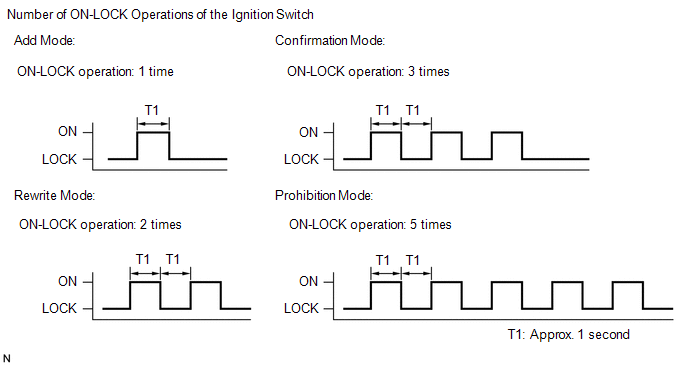
(4) Turn the ignition switch from LOCK to ON and back to LOCK at approximately 1-second intervals 1 to 5 times to select a mode (see the illustration). Then remove the key from the ignition key cylinder.
HINT:
Complete this procedure within 40 seconds.
NOTICE:
If the number of the ON-LOCK operations of the ignition switch is 0, 4, 6 or more, there will be no response to inform which mode has been selected.
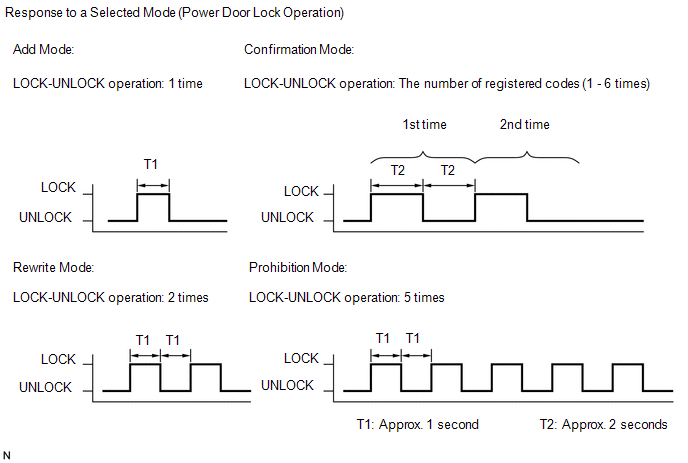
(5) After selecting a mode, the main body ECU (driver side junction block assembly) automatically performs the power door LOCK- UNLOCK operation within 5 seconds to inform the selected mode (see the illustration).
HINT:
- In confirmation mode, the LOCK- UNLOCK operation will occur once for each recognition code that has been registered. For example, if 2 recognition codes have been registered, the LOCK-UNLOCK operation will occur 2 times.
- In confirmation mode and prohibition mode, once a LOCK-UNLOCK operation response has occurred, the registration procedure will end.
(c) Register new recognition codes (Add mode or Rewrite mode):
(1) Within 45 seconds after add mode or rewrite mode has been selected, press the LOCK and UNLOCK switches on the transmitter switch simultaneously for 1.0 to 1.5 seconds.
Then, press either one of the switches for more than 1.0 second. (Procedure "A")
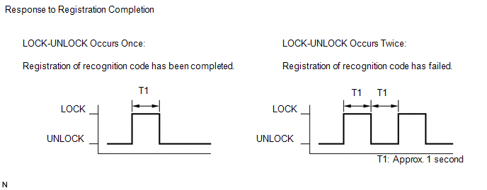
(2) Within 5 seconds after the transmitter switch has been released, the LOCK-UNLOCK operation will be automatically performed once if the registration of the recognition code of the transmitter is completed correctly.
If the LOCK-UNLOCK operation is performed twice, registration of the recognition code has failed. Perform the registration procedure from the beginning. (Procedure "B")
(3) If multiple transmitters need to be registered, repeat procedures "A" and "B" within 45 seconds each.
HINT:
- Up to the maximum registration number can be registered at once.
- If even one of the following conditions is met, registration mode will
end.
- 40 seconds have elapsed after a recognition code has been registered.
- Any of the doors are opened.
- The key is inserted into the ignition key cylinder.
- The maximum registration number.
2. REGISTRATION OF RECOGNITION CODE (USING TECHSTREAM)
(a) Turn the ignition switch to ON.
(b) Select either add or rewrite mode according to the Techstream display.
(c) The number of registered codes is indicated.
(d) Registration of the door control transmitter.
(1) If either add mode or rewrite mode has been selected, press the LOCK and UNLOCK switches on the transmitter simultaneously.
(2) Within 3 seconds of releasing the LOCK and UNLOCK switches, press either of the switches on the door control transmitter.
NOTICE:
- Do not press the LOCK and UNLOCK switches simultaneously for more than 1.5 seconds.
- Perform this operation within 1 meter of the driver seat to register the transmitter.
- Do not push other transmitter switches during the transmitter registration process.
(3) The main body ECU (driver side junction block assembly) automatically performs the power door LOCK-UNLOCK operation once in order to indicate whether registration has been completed correctly or not.
(4) If continuing registration, the next recognition code must be registered in the door control transmitter within 30 seconds.
HINT:
Up to 6 recognition codes can be registered.
(e) Completing the registration mode.
(1) Registration mode will end when any of the following occurs:
- 30 seconds or more have elapsed after a code is registered.
- The Techstream is used to finish registration.
- The Techstream is disconnected.
- The ignition switch is turned off.
(f) Perform the following after registration is completed.
(1) Perform the wireless door lock control operation check (See page
.gif) ).
).
HINT:
If the wireless door lock control does not operate, perform the registration procedure again.
 Customize Parameters
CUSTOMIZE PARAMETERS
HINT:
The following items can be customized.
NOTICE:
When the customer requests a change in a function, first make sure that
the function can be customized.
Be ...
 Problem Symptoms Table
PROBLEM SYMPTOMS TABLE
HINT:
Use the table below to help determine the cause of problem symptoms.
If multiple suspected areas are listed, the potential causes of the symptoms
are lis ...
Other materials about Toyota Venza:
Diagnosis System
DIAGNOSIS SYSTEM
1. DESCRIPTION
(a) Sliding roof system data and Diagnostic Trouble Codes (DTCs) can be read
through the vehicle Data Link Connector 3 (DLC3). When the system seems to be malfunctioning,
use the Techstream to check for malfunctions and pe ...
Fuel Sender Gauge Assembly
Components
COMPONENTS
ILLUSTRATION
Removal
REMOVAL
PROCEDURE
1. DISCHARGE FUEL SYSTEM PRESSURE
(a) Discharge fuel system pressure (See page
).
2. DISCONNECT CABLE FROM NEGATIVE BATTERY TERMINAL
NOTICE:
When disconnecting the cable, some syste ...
Installation
INSTALLATION
CAUTION / NOTICE / HINT
HINT:
Use the same procedure for the LH side and RH side.
The following procedure listed below is for the LH side.
PROCEDURE
1. SECURE FRONT SHOCK ABSORBER ASSEMBLY
(a) Install the bolt an ...

0.1775