
Toyota Venza: Runnable Signal Malfunction (B2286,P0335)
DESCRIPTION
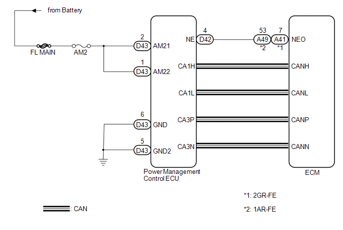
The power management control ECU receives an engine speed signal and information that indicates whether the engine is running or not. It receives the engine speed signal from the ECM via a direct line, and the information about whether the engine is running is received from the ECM via CAN. If the information sent using these 2 methods is inconsistent, this DTC will be stored.
|
DTC No. |
DTC Detection Condition |
Trouble Area |
|---|---|---|
|
B2286 |
Information received by the power management control ECU via a direct line from the ECM and information received from the ECM via CAN is inconsistent. |
|
|
P0335 |
Information received by the power management control ECU via a direct line from the ECM and information received from the ECM via CAN is inconsistent. |
Wire harness or connector |
WIRING DIAGRAM
CAUTION / NOTICE / HINT
NOTICE:
- When the power management control ECU is replaced with a new one and the cable from the negative (-) battery terminal is connected, the power source mode becomes the on (IG) mode. When the battery is removed and reinstalled, the power source mode that was selected when the battery was removed is restored.
- Inspect the fuses for circuits related to this system before performing the following inspection procedure.
HINT:
Check the connector connection to the terminal to make sure that there is no abnormality such as a loose connection, deformation, etc.
PROCEDURE
|
1. |
CHECK HARNESS AND CONNECTOR (BATTERY - POWER MANAGEMENT CONTROL ECU) |
.gif)
| NG | .gif) |
REPAIR OR REPLACE HARNESS OR CONNECTOR (BATTERY - POWER MANAGEMENT CONTROL ECU) |
|
.gif)
|
2. |
CHECK HARNESS AND CONNECTOR (POWER MANAGEMENT CONTROL ECU - BODY GROUND) |
| NG | |
REPAIR OR REPLACE HARNESS OR CONNECTOR (POWER MANAGEMENT CONTROL ECU - BODY GROUND) |
|
|
3. |
CHECK HARNESS AND CONNECTOR (POWER MANAGEMENT CONTROL ECU - ECM) |
(a) Disconnect the A41 connector from the ECM.
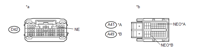
(b) Measure the resistance according to the value(s) in the table below.
Standard Resistance:
|
Tester Connection |
Condition |
Specified Condition |
|---|---|---|
|
D42-4 (NE) - A41-7 (NEO)*1 D42-4 (NE) - A49-53 (NEO)*2 |
Always |
Below 1 Ω |
|
D42-4 (NE) - Body ground |
Always |
10 kΩ or higher |
- *1: for 2GR-FE
- *2: for 1AR-FE
|
*a |
Front view of wire harness connector (to Power Management Control ECU) |
*b |
Front view of wire harness connector (to ECM) |
|
*A |
for 2GR-FE |
*B |
for 1AR-FE |
| NG | |
REPAIR OR REPLACE HARNESS OR CONNECTOR (POWER MANAGEMENT CONTROL ECU - ECM) |
|
|
4. |
READ VALUE USING TECHSTREAM |
(a) Connect the Techstream to the DLC3.
(b) Turn the engine switch on (IG).
(c) Turn the Techstream on.
(d) Enter the following menus: Body Electrical / Power Source Control / Data List.
(e) Read the Data List according to the value(s) in the Techstream.
Power Source Control|
Tester Display |
Measurement Item/Range |
Normal Condition |
Diagnostic Note |
|---|---|---|---|
|
Engine Condition |
Engine condition/Stop or Run |
Stop: Engine stopped Run: Engine running |
- |
OK:
Stop (engine is stopped) and Run (steering lock is locked) appear on the screen.
| NG | |
GO TO SFI SYSTEM |
|
|
5. |
CHECK POWER MANAGEMENT CONTROL ECU |
|
(a) Reconnect the D42 connector to the power management control ECU. |
|
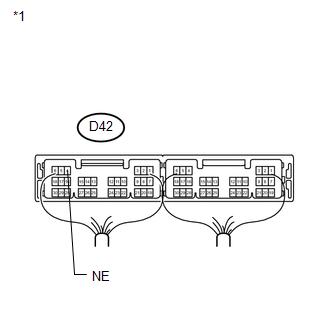
(b) Reconnect the A41 connector to the ECM.
(c) Connect a D42-4 (NE) and body ground.
(d) Check for pulses according to the condition(s) in the table below.
OK:
|
Tester Connection |
Condition |
Specified Condition |
|---|---|---|
|
D42-4 (NE) - Body ground |
Engine is stopped |
No pulse generated |
|
Engine is running |
Pulse generated (1000 rpm: 200 Hz) |
|
*1 |
Component with harness connected (Power Management Control ECU) |
| OK | |
REPLACE POWER MANAGEMENT CONTROL ECU |
| NG | |
GO TO SFI SYSTEM |
 Lost Communication with ECM / PCM "A" (U0100)
DESCRIPTION
The power management control ECU receives shift position information from 2 sources.
It receives a shift position P signal from the shift lock control unit assembly
via a direct line, ...
 Vehicle Speed Signal Malfunction (B2282)
DESCRIPTION
The power management control ECU receives vehicle speed information using 2 methods.
It receives a speed signal from the meter ECU. It also receives speed information
from the meter E ...
Other materials about Toyota Venza:
Lost Communication with ECM / PCM "A" (U0100,U0129)
DESCRIPTION
The power steering ECU receives signals from the ECM and the brake actuator assembly
(skid control ECU) via the CAN communication system.
DTC No.
DTC Detection Condition
Trouble Area
U0100
...
ABS Malfunction (C1296/96)
DESCRIPTION
If a malfunction in the speed sensor signal circuit occurs, the AWD control ECU
will output this DTC.
DTC No.
DTC Detecting Condition
Trouble Area
C1296/96
When condition is met:
...
Diagnostic Trouble Code Chart
DIAGNOSTIC TROUBLE CODE CHART
HINT:
If a trouble code is output during the DTC check, inspect the trouble areas listed
for that code. For details of the code, refer to "See page" in the DTC chart.
Inspect the fuses and relays before troub ...

0.114