Toyota Venza: Tire Pressure Warning Ecu
Components
COMPONENTS
ILLUSTRATION
ILLUSTRATION
Removal
REMOVAL
CAUTION / NOTICE / HINT
NOTICE:
Before removing the tire pressure warning ECU, read the registered transmitter
IDs of all wheels and write them down to use for re-registration of transmitter
IDs (See page .gif) ).
).
PROCEDURE
1. DISCONNECT CABLE FROM NEGATIVE BATTERY TERMINAL
NOTICE:
When disconnecting the cable, some systems need to be initialized after the cable
is reconnected (See page ).
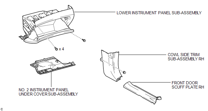
2. REMOVE FRONT DOOR SCUFF PLATE RH
3. REMOVE COWL SIDE TRIM SUB-ASSEMBLY RH
4. REMOVE NO. 2 INSTRUMENT PANEL UNDER COVER SUB-ASSEMBLY
5. REMOVE LOWER INSTRUMENT PANEL SUB-ASSEMBLY
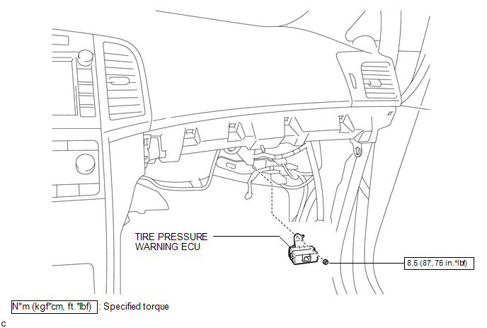
6. REMOVE TIRE PRESSURE WARNING ECU
|
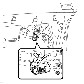
(a) Remove the nut. |
|
|
(b) Disconnect the connector to remove the tire pressure warning ECU. |
|
Installation
INSTALLATION
PROCEDURE
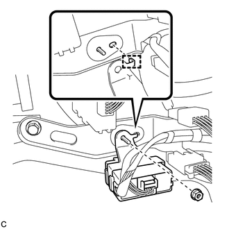
1. INSTALL TIRE PRESSURE WARNING ECU
|
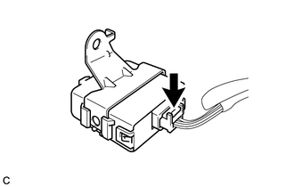
(a) Connect the connector to the tire pressure warning ECU. |
|
.png)
|
(b) Install the tire pressure warning ECU with the nut. Torque: 8.5 N·m {87 kgf·cm, 75 in·lbf} HINT: Engage the tab into the hole as shown in the illustration to install the tire pressure warning ECU. |
|
2. INSTALL LOWER INSTRUMENT PANEL SUB-ASSEMBLY
.gif)
3. INSTALL NO. 2 INSTRUMENT PANEL UNDER COVER SUB-ASSEMBLY
4. INSTALL COWL SIDE TRIM SUB-ASSEMBLY RH
5. INSTALL FRONT DOOR SCUFF PLATE RH
6. CONNECT CABLE TO NEGATIVE BATTERY TERMINAL
NOTICE:
When disconnecting the cable, some systems need to be initialized after the cable
is reconnected (See page ).
7. REGISTER TRANSMITTER ID
HINT:
It is necessary to register all transmitter IDs (See page
).
8. INSPECT TIRE PRESSURE WARNING SYSTEM
(a) Inspect the tire pressure warning system (See page
).

 Tire Pressure Warning Receiver
Components
COMPONENTS
ILLUSTRATION
Removal
REMOVAL
PROCEDURE
1. DISCONNECT CABLE FROM NEGATIVE BATTERY TERMINAL
NOTICE:
When disconnecting the cable, some systems need to be initialized ...
Other materials about Toyota Venza:
Basic Inspection
BASIC INSPECTION
When the malfunction is not confirmed by the DTC check, troubleshooting should
be carried out in all circuits considered to be possible causes of the problem.
In many cases, by carrying out the basic engine check shown in the following pr ...
Problem Symptoms Table
PROBLEM SYMPTOMS TABLE
HINT:
Use the table below to help determine the cause of problem symptoms.
If multiple suspected areas are listed, the potential causes of the symptoms
are listed in order of probability in the "Suspected Area" ...
Steering Lock Position Signal Circuit Malfunction (B2285)
DESCRIPTION
This DTC is stored when serial communication signals and LIN communication signals
in the circuit between the power management control ECU and steering lock actuator
assembly (steering lock ECU) are inconsistent.
DTC No.
...

0.1426