Toyota Venza: System Diagram
SYSTEM DIAGRAM
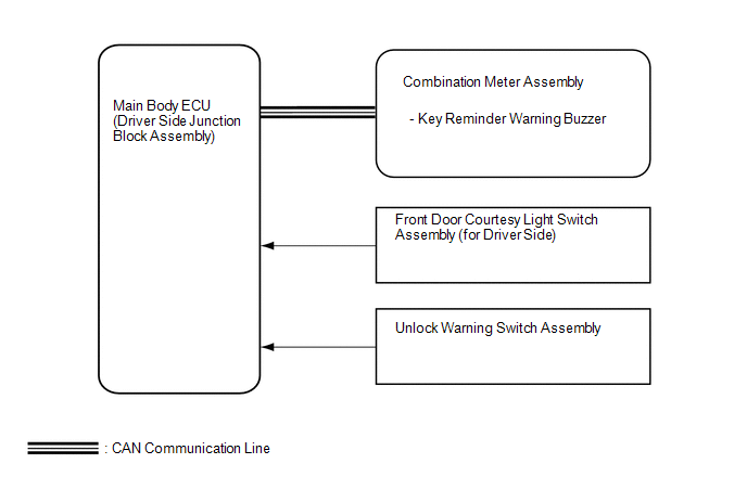 Communication Table
|
Sender |
Receiver |
Signal |
Communication Method |
|---|---|---|---|
|
Main Body ECU (Driver Side Junction Block Assembly) |
Combination Meter Assembly |
Driver side door courtesy light switch signal |
CAN |
|
Main Body ECU (Driver Side Junction Block Assembly) |
Combination Meter Assembly |
Unlock warning switch signal |
CAN |
 Parts Location
PARTS LOCATION
ILLUSTRATION
...
 System Description
SYSTEM DESCRIPTION
1. KEY REMINDER WARNING SYSTEM DESCRIPTION
(a) When the driver side door is opened with the key in ACC or LOCK, this system
causes a buzzer to sound in order to warn the driver ...
Other materials about Toyota Venza:
Power Window Switch Malfunction (B2312)
DESCRIPTION
The power window regulator motor assembly is operated by the power window regulator
master switch assembly or power window regulator switch assembly. The power window
regulator motor assembly has motor, regulator and ECU functions.
This DTC i ...
Fuel pump shut off system
To minimize the risk of fuel leakage when the engine stalls or an airbag inflates
upon collision, the fuel pump shut off system stops supplying fuel to the engine.
Follow the procedure below to restart the engine after the system is activated.
►Vehic ...
Transmitter ID not Received in Main Mode (C2126/26)
DESCRIPTION
After all IDs are registered, DTC C2126/26 is set in the tire pressure warning
ECU and the tire pressure warning light blinks for 1 minute and then comes on.
When the tire pressure warning ECU successfully receives radio waves from all
the tr ...

0.2247