Toyota Venza: Relay
On-vehicle Inspection
ON-VEHICLE INSPECTION
PROCEDURE
1. INSPECT TAILLIGHT RELAY (TAIL)
|
(a) Remove the taillight relay from the main body ECU (driver side junction block assembly). |
|
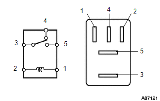
(b) Measure the resistance according to the value(s) in the table below.
Standard Resistance:
|
Tester Connection |
Condition |
Specified Condition |
|---|---|---|
|
3 - 5 |
Battery voltage applied to terminals 1 and 2 |
Below 1 Ω |
|
Battery voltage not applied between terminals |
10 kΩ or higher |
|
|
3 - 4 |
Battery voltage applied to terminals 1 and 2 |
10 kΩ or higher |
|
Battery voltage not applied between terminals |
Below 1 Ω |
If the result is not as specified, replace the taillight relay.
2. INSPECT FOG LIGHT RELAY (FOG)
|
(a) Remove the fog light relay from the main body ECU (driver side junction block assembly). |
|
.png)
(b) Measure the resistance according to the value(s) in the table below.
Standard Resistance:
|
Tester Connection |
Condition |
Specified Condition |
|---|---|---|
|
3 - 5 |
Battery voltage applied to terminals 1 and 2 |
Below 1 Ω |
|
3 - 5 |
Battery voltage not applied between terminals |
10 kΩ or higher |
If the result is not as specified, replace the fog light relay.
3. INSPECT BI-XENON RELAY
|
(a) Remove the BI-XENON relay from the power distributor (engine room junction block assembly). |
|
.png)
(b) Measure the resistance according to the value(s) in the table below.
Standard Resistance:
|
Tester Connection |
Condition |
Specified Condition |
|---|---|---|
|
3 - 5 |
Battery voltage applied to terminals 1 and 2 |
Below 1 Ω |
|
3 - 5 |
Battery voltage not applied between terminals |
10 kΩ or higher |
If the result is not as specified, replace the BI-XENON relay.
 Rear Light Assembly
Components
COMPONENTS
ILLUSTRATION
On-vehicle Inspection
ON-VEHICLE INSPECTION
PROCEDURE
1. INSPECT REAR LIGHT ASSEMBLY
(a) Disconnect the connector from the rear light assembl ...
 Side Turn Signal Light Assembly
Components
COMPONENTS
ILLUSTRATION
Removal
REMOVAL
CAUTION / NOTICE / HINT
HINT:
Use the same procedure for the RH and LH sides.
The procedure described below is for the LH si ...
Other materials about Toyota Venza:
Tire size
- Typical tire size information
The illustration indicates typical tire size.
1. Tire use
(P = Passenger car, T = Temporary use)
2. Section width (millimeters)
3. Aspect ratio
(tire height to section width)
4. Tire construction code
(R = Radial ...
Fail-safe Chart
FAIL-SAFE CHART
1. Fail-safe
This function minimizes the loss of operation when any abnormality occurs in
a sensor or solenoid.
Fail-safe Control List
Malfunction Part
Function
Input Turbine Speed Sensor
...
Removal
REMOVAL
CAUTION / NOTICE / HINT
HINT:
Use the same procedure for the RH side and LH side.
The procedure listed below is for the LH side.
PROCEDURE
1. PRECAUTION
CAUTION:
Be sure to read Precaution thoroughly before servicing (See page
...

0.1243