Toyota Venza: Air conditioning filter
The air conditioning filter must be changed regularly to maintain air conditioning efficiency.
- Removal method
 Vehicles with smart key system:
Turn the “ENGINE START STOP” switch off.
Vehicles without smart key system:
Turn the engine switch to the “LOCK” position.
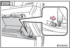
Open the glove box. Slide off the damper.
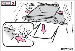
Push each side of the glove box to release the pins. Then disconnect the claws at the bottom and remove the glove box.
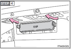
Remove the filter cover.
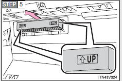
Remove the air conditioning filter and replace it with a new one.
The “↑UP” marks shown on the filter should be pointing up.
- Checking interval
Inspect and replace the air conditioning filter according to the maintenance schedule. In dusty areas or areas with heavy traffic flow early replacement may be required. (For scheduled maintenance information, refer to the “Scheduled Maintenance Guide”, “Owner’s Manual Supplement”.)
- If air flow from the vents decreases dramatically
The filter may be clogged. Check the filter and replace if necessary.
NOTICE
- To prevent damage to the system
When using the air conditioning system, make sure that a filter is always installed.
 Wheels
If a wheel is bent, cracked or heavily corroded, it should be replaced.
Otherwise, the tire may separate from the wheel or cause loss of handling control.
- Wheel selection
When replacing whe ...
 Key battery
Replace the battery with a new one if it is discharged.
- You will need the following items:
• Flathead screwdriver (To prevent damage to the key, cover the tip of the screwdriver
with rag ...
Other materials about Toyota Venza:
Installation
INSTALLATION
PROCEDURE
1. REPAIR INSTRUCTION
2. INSTALL REAR DOOR LOWER OUTSIDE STRIPE
(a) Refer to the illustration to position the rear door lower outside stripe.
Standard Measurement
Dimension
Measurement
A
...
Registration
REGISTRATION
PROCEDURE
1. DESCRIPTION OF CODE REGISTRATION
HINT:
The ID codes are the same as recognition codes for the wireless transmitter
and the engine immobiliser function. Registering an ID code enables the
smart key system, the wirel ...
BUS IC Communication Malfunction (B1497/97)
DESCRIPTION
The air conditioning harness connects the A/C amplifier and each servo. The A/C
amplifier supplies power and sends operation instructions to each servo through
the air conditioning harness. Each servo sends the damper position information to
...

0.1202